Mitsubishi Colt Ralliart. Manual - part 307
TROUBLESHOOTING
CONTROLLER AREA NETWORK (CAN)
54D-57
POSSIBLE CAUSES
• Damaged harness wires and connectors
• Malfunction of the combination meter (incorporat-
ing meter-A/C-ECU)
• Malfunction of the engine-ECU <M/T> or
engine-CVT-ECU <CVT>
DIAGNOSIS PROCEDURE
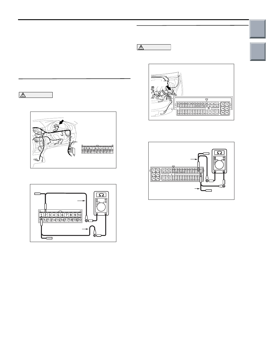
STEP 1. Resistance measurement at B-15
combination meter connector.
CAUTION
A digital multimeter should be used. For details
refer to
AC401055
AE
Connector: B-15
B-15 (B)
Harness side
(1) Remove the combination meter, and measure at
the equipment side.
AC204738FM
Equipment side: B-15
Test
harness
Test
harness
(2) Resistance between B-15 combination meter
connector terminal Nos.1 and 2
OK: 120
± 20 Ω
Q: Is the check result normal?
YES :
<Within 120
± 20 Ω> Go to Step 2.
NO :
<Not within 120
± 20 Ω> Replace the
combination meter.
STEP 2. Resistance measurement at A-08
engine-ECU <M/T> or engine-CVT-ECU <CVT>
connector.
CAUTION
A digital multimeter should be used. For details
refer to
AC509191
Connector: A-08
Harness side
AD
A-08 (GR)
(1) Remove the engine-ECU <M/T> or
engine-CVT-ECU <CVT>, and measure at the
equipment side.
AC204738
AC204738FT
Equipment side: A-08
Test
harness
Test
harness
(2) Resistance at A-08 engine-ECU <M/T> or
engine-CVT-ECU <CVT> connector terminal
Nos.105 and 106
OK: 120
± 20 Ω
Q: Is the check result normal?
YES :
<Within 120
± 20 Ω> Repair the wiring
harness between combination meter
connector and engine-ECU <M/T> or
engine-CVT-ECU <CVT> connector.
NO :
<Not within 120
± 20 Ω> Replace the
engine-ECU <M/T> or engine-CVT-ECU
<CVT>.
Main
Index
Group
TOC