Mitsubishi Colt Ralliart. Manual - part 269


  Index      Mitsubishi     Mitsubishi Colt Ralliart - service repair manual


Search            


Content   ..  267  268  269  270   ..


Mitsubishi Colt Ralliart. Manual - part 269


PISTON AND CONNECTING ROD

ENGINE OVERHAUL <4A9>

11B-40

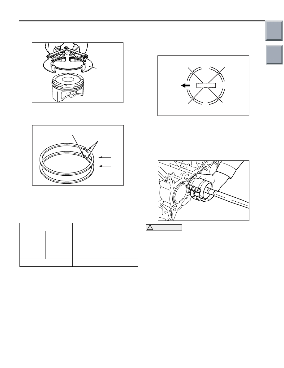
>>C<< PISTON RING NO. 2 / PISTON 
RING NO. 1 INSTALLATION

AK304892AB

Piston ring
expander

Use a piston ring expander to install the No. 1 and 
No. 2 piston rings. The ring identification mark should 
face upwards.

AK402172

No. 2

AC

No. 1

Size marks

Identification mark

Identification mark

No. 1 ring: None
No. 2 ring: 2R

NOTE: Each of the available piston rings has a size 
mark as follows:

Size

Size mark

Standard No. 1 ring No mark

 (Yellow paint on periphery)

No. 2 ring No mark

 (Yellow paint on periphery)

0.25 mm oversize

25

>>D<< PISTON, CONNECTING ROD 
ASSEMBLY INSTALLATION

1. Apply engine oil sufficiently onto the piston 

periphery, the piston rings and the oil ring.

AK202730

No. 1

No. 2

Side rail

Side rail

AC

Piston pin

2. Align the gaps of the piston rings and the oil ring 

(side rails, spacer) as illustrated.

3. Insert the piston and connecting rod assembly 

from above the cylinder block and through the 
cylinder bore, ensuring that the front mark on the 
piston top faces the camshaft sprocket.

AK304957

CAUTION

Do not try to strike hard on the assembly to fit it 
in place as this will break the piston rings.
4. While firmly holding the piston rings with a ring 

band, insert the piston and connecting rod 
assembly into place.

Main

Index

Group

TOC

PISTON AND CONNECTING ROD

ENGINE OVERHAUL <4A9>

11B-41

>>E<< CONNECTING ROD BEARING 
INSTALLATION

AK305607AB

Identification
color

1. Connecting rod bearings are color coded with 

paint at the illustrated locations. Bearings should 
be selected based on the following table.

Connecting rod bearing
Upper bearing

Lower bearing

Blue

Red

Red

Blue

Yellow or black

Yellow or black

Example: If a blue upper bearing is selected, the 
lower bearing must be red.

2. Install the bearings selected onto the connecting 

rod big end and the bearing cap.

AK306100

AB

A

B

3. Measure the illustrated location. The error should 

be within 0.5 mm.

>>F<< CONNECTING ROD CAP 
INSTALLATION

AK304890AC

Cylinder No.

Front mark

1. Install the correct bearing cap onto the 

corresponding connecting rod, based on the 
marking placed during disassembly.

AK304900

2. Ensure that the thrust clearance of the connecting 

rod big end is to specification.

Standard value: 0.10 

 0.35 mm

Limit: 0.4 mm

Main

Index

Group

TOC

PISTON AND CONNECTING ROD

ENGINE OVERHAUL <4A9>

11B-42

>>G<< CONNECTING ROD CAP BOLT 
INSTALLATION

1. Inspect all reused connecting rod bolts according 

to the following procedure.

AK401052

AB

15 mm

30 mm

(1) Measure the outside diameter at 15 mm and 

30 mm from the head of the connecting rod 
bolts shown in Figure respectively.

(2) When the difference between the outside 

diameters (measured at 15 mm and 30 mm) 
exceeds the standard value, replace the 
connecting rod bolts.

Standard value: 0 

 0.1 mm

2. Apply engine oil to the threaded portion and 

seating face of the bolt.

3. To correctly install the cap, loosely install the bolts 

with fingers.

4. Alternately, tighten the bolts in several steps to the 

specified torque of 15 

± 2 N⋅m.

AK304894AC

90˚ to 94˚ 

Paint
mark

Paint
mark

5. Put a paint mark on the bolt head as illustrated.
6. Put another paint mark on the bolt head at 90 to 

94 degree angle in the tightening direction from 
the first paint mark.

CAUTION

• If the bolt is tightened less than the specified 

lower limit of 90 degree angle, the bolt may 
become loose. Be sure to tighten correctly.

• If the bolt is tightened in excess of the speci-

fied upper limit of 94 degree angle, loosen the 
bolt completely and repeat the entire proce-
dures.

7. Tighten the bolt 90 to 94 degree angle. The paint 

mark on the connecting rod should be aligned 
with the paint mark on the bolt.

Main

Index

Group

TOC

PISTON AND CONNECTING ROD

ENGINE OVERHAUL <4A9>

11B-43

INSPECTION

M1113008500837

PISTON RING

AK304899

1. Measure the clearance between the piston ring 

and the ring groove. If the measured value 
exceeds the limit, replace the piston ring, or both 
the piston and the piston ring.

Standard value: 

No. 1 ring: 0.03 

 0.07 mm

No. 2 ring: 0.02 

 0.06 mm

Limit: 0.1 mm

AK305608AB

End gap

Piston ring

Press down ring
with piston

2. Insert the piston ring into the cylinder bore. Insert 

the piston with the top face end first into the 
cylinder bore, pushing the piston ring and 
positioning it squarely with the cylinder bore. 
Then, measure the piston ring end gap using a 
feeler gauge. If the measured value exceeds the 
limit, replace the piston ring.

Standard value: 

No. 1 ring: 0.15 

 0.30 mm

No. 2 ring: 0.20 

 0.40 mm

Oil ring: 0.10 

 0.40 mm

Limit: 

No. 1 ring: 0.8 mm
No. 2 ring: 0.8 mm
Oil ring: 1.0 mm

CRANKSHAFT PIN OIL CLEARANCE 
(PLASTIGAGE METHOD)

1. Wipe off oil from the crankshaft pin and the 

connecting rod bearings.

2. Place a plastigage, with a length equal to the 

bearing width, onto the crank pin in the axial 
direction.

AK304897AB

Plastigage

3. Carefully install the connecting rod cap over the 

plastigage, and tighten the bolts to 15 

± 2 N⋅m → 

+ 90 to 94 degree angle.

4. Remove the bolts. Slowly remove the connecting 

rod cap.

AK304898AB

Plastigage

5. Using the measure printed on the plastigage 

package, measure the width (widest portion) of 
the crushed plastigage.

Standard value: 0.014 

 0.059 mm

Limit: 0.1 mm

Main

Index

Group

TOC


Content   ..  267  268  269  270   ..