Mitsubishi Colt Ralliart. Manual - part 218


  Index      Mitsubishi     Mitsubishi Colt Ralliart - service repair manual


Search            


Content   ..  216  217  218  219   ..


Mitsubishi Colt Ralliart. Manual - part 218


ON-VEHICLE SERVICE

BASIC BRAKE SYSTEM

35A-18

(3) If the axial play exceeds the limit, disassemble 

the hub assembly to check each part.

(4) If the axial play does not exceed the limit, 

dephase the brake disc and secure it. Then 
recheck the brake disc run-out.

CAUTION

• After a new brake disc is installed, always 

grind the brake disc with on-the-car type 
brake lathe. If this step is not carried out, the 
brake disc run-out exceeds the specified 
value, resulting in judder.

AC006226AD

M12 Flat washer

M12 Flat washer

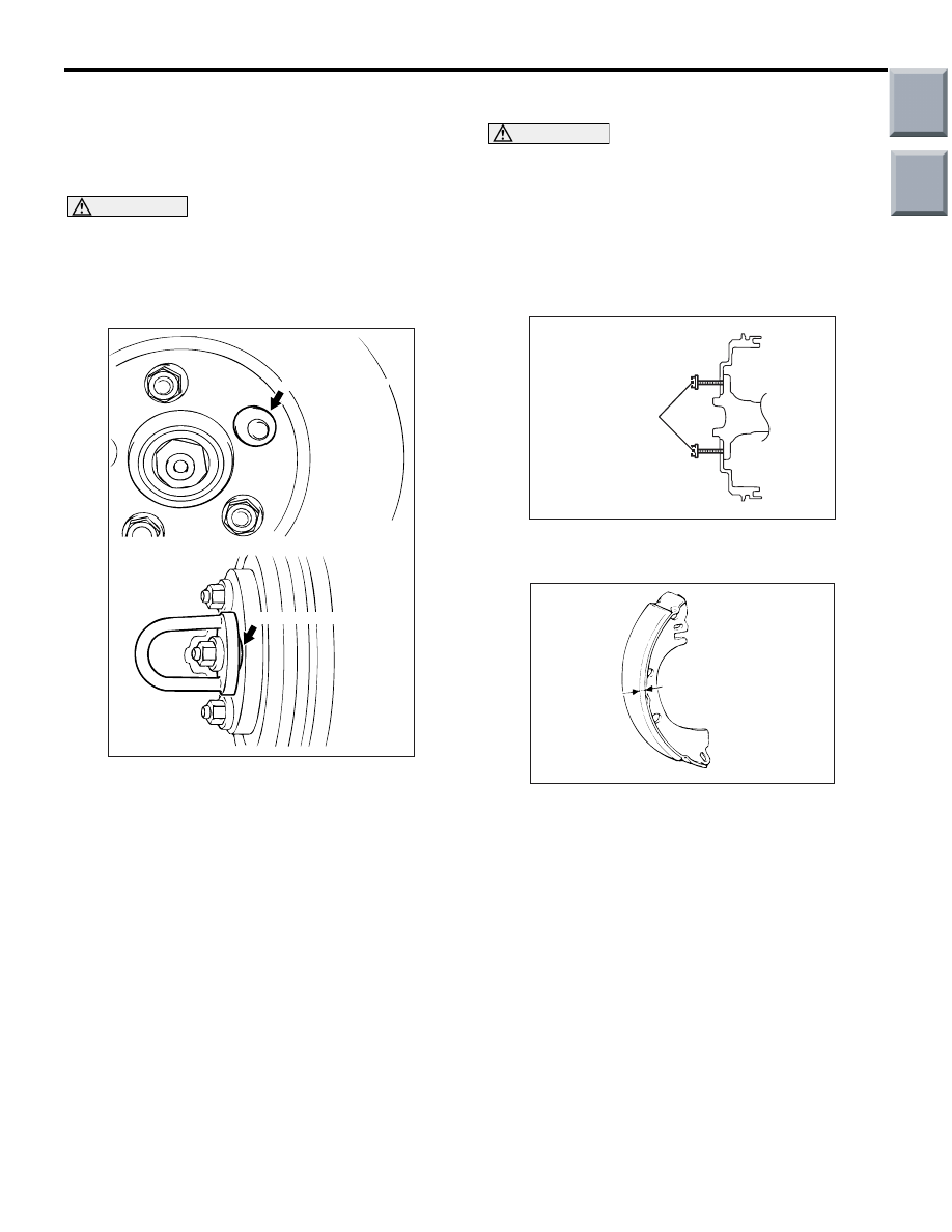
When the on-the-car type lathe is used, first 

install M12 flat washer on the stud bolt in the 
brake disc side according to the figure, and 
then install the adapter. If the adapter is 
installed with M12 flat washer not seated, the 
brake disc rotor may be deformed, resulting 
in inaccurate grinding.

• Grind the brake disc with all wheel nuts diag-

onally and equally tightened to the specified 
torque 100 N

m. When all numbers of wheel 

nuts are not used, or the tightening torque is 
excessive or not equal, the brake disc rotor or 
drum may be deformed, resulting in judder.

5. If the run-out cannot be corrected by changing the 

phase of the brake disc, replace the brake disc or 
grind it with the on-the-car type brake lathe 
("MAD, DL-8700PF" or equivalent).

BRAKE LINING THICKNESS CHECK

M1351003000527

CAUTION

• Whenever the shoe and lining assembly is 

replaced, replace both RH and LH assemblies 
as a set to prevent the car from pulling to one 
side when braking.

• If there is a significant difference in the thick-

ness of the shoe and lining assemblies on the 
left and right sides, check the sliding condi-
tion of the piston.

AC207894 AB

Bolts
(M8 x 1.25)

1. Use M8

×1.25 bolts as shown to remove the brake 

drum by tightening them evenly.

ACX00708

A

AF

2. Measure the thickness of the brake lining at the 

area with the worst wear.

Standard value: 4.0 mm
Minimum limit: 1.0 mm

3. Replace the shoe and lining assembly if the brake 

lining thickness is less than the limit or if it is not 
worn evenly. For installation procedures for the 
shoe and lining assembly, refer to 

P.35A-50

.

Main

Index

Group

TOC

ON-VEHICLE SERVICE

BASIC BRAKE SYSTEM

35A-19

BRAKE DRUM INSIDE DIAMETER CHECK

M1351003200576

AC207894 AB

Bolts
(M8 x 1.25)

1. Use M8

×1.25 bolts as shown to remove the brake 

drum by tightening them evenly.

AC000893

2. Measure the inside diameter of the brake drum at 

two or more locations.

Standard value: 203 mm
Limit: 205 mm

3. Replace the brake drums, shoe and lining 

assembly when wear exceeds the limit value or is 
badly imbalanced.

BRAKE LINING AND BRAKE DRUM 
CONTACT CHECK

M1351003100375

1. Remove the brake drum.
2. Remove the shoe and lining assembly (Refer to 

P.35A-50

).

AC000856

3. Chalk the inner surface of the brake drum and rub 

with the shoe and lining assembly.

4. Replace the shoe and lining assembly or brake 

drums if there are any irregular contact areas.
NOTE: Clean off chalk after check.

Main

Index

Group

TOC

BRAKE PEDAL

BASIC BRAKE SYSTEM

35A-20

BRAKE PEDAL

REMOVAL AND INSTALLATION <EXCEPT 
FOR RALLIART VERSION-R>

M1351003400848

Post-installation Operation
• Brake Pedal Adjustment (Refer to 

P.35A-7

).

AC601323AB

14 ± 2 N·m

12 ± 2 N·m

6

1

2

3

4

5

8

7

9

11

10 <CVT>

10 <M/T>

20 ± 3 N·m

Removal steps 

Steering column cover <CVT>

Shift lock rod connection <CVT> 
(Refer to GROUP 23A, CVT Key 
Interlock and Shift Lock Mechanism 

P.23A-148

).

Shift lock unit <CVT> (Refer to 
GROUP 23A, CVT Key Interlock and 
Shift Lock Mechanis

P.23A-148

).

1. Split pin <CVT>
2. Shift lock cable connection <CVT>
3. Harness connector
4. Stop lamp switch
5. Pedal clip
6. Pedal stopper
7. Snap pin
8. Pin assembly

>>

A

<< 9. Reinforced bracket

10. Pedal pad

>>

A

<< 11. Brake pedal assembly

INSTALLATION SERVICE POINTS
>>A<< BRAKE PEDAL ASSEMBLY/REIN-
FORCED BRACKET INSTALLATION

1. Temporarily tighten the brake pedal assembly.
2. Temporarily tighten the reinforced bracket.

AC206174AC

A

B

C

Reinforced 
bracket

A

3. Tighten the mounting nuts and bolts in 

alphabetical order shown in the illustration.

Main

Index

Group

TOC

BRAKE PEDAL

BASIC BRAKE SYSTEM

35A-21

REMOVAL AND INSTALLATION 
<RALLIART VERSION-R>

M1351003400837

Post-installation Operation
• Brake Pedal Adjustment (Refer to 

P.35A-7

).

AC601052AC

14 ± 2 N·m

12 ± 2 N·m

3

1

2

5

4

6

8

7

20 ± 3 N·m

Removal steps 

1.

Harness connector

>>

B

<<

2.

Stop lamp switch

3.

Pedal stopper

4.

Snap pin

5.

Pin assembly

>>

A

<<

6.

Reinforced bracket

7.

Pedal pad

>>

A

<<

8.

Brake pedal assembly

INSTALLATION SERVICE POINTS
>>A<< BRAKE PEDAL ASSEMBLY/REIN-
FORCED BRACKET INSTALLATION

1. Temporarily tighten the brake pedal assembly.
2. Temporarily tighten the reinforced bracket.

AC601387AC

A

B

C

Reinforced 
bracket

A

3. Tighten the mounting nuts and bolts in 

alphabetical order shown in the illustration.

Main

Index

Group

TOC


Content   ..  216  217  218  219   ..