Mitsubishi Colt Ralliart. Manual - part 177


  Index      Mitsubishi     Mitsubishi Colt Ralliart - service repair manual


Search            


Content   ..  175  176  177  178   ..


Mitsubishi Colt Ralliart. Manual - part 177


TROUBLESHOOTING <CVT>

CVT

23A-51

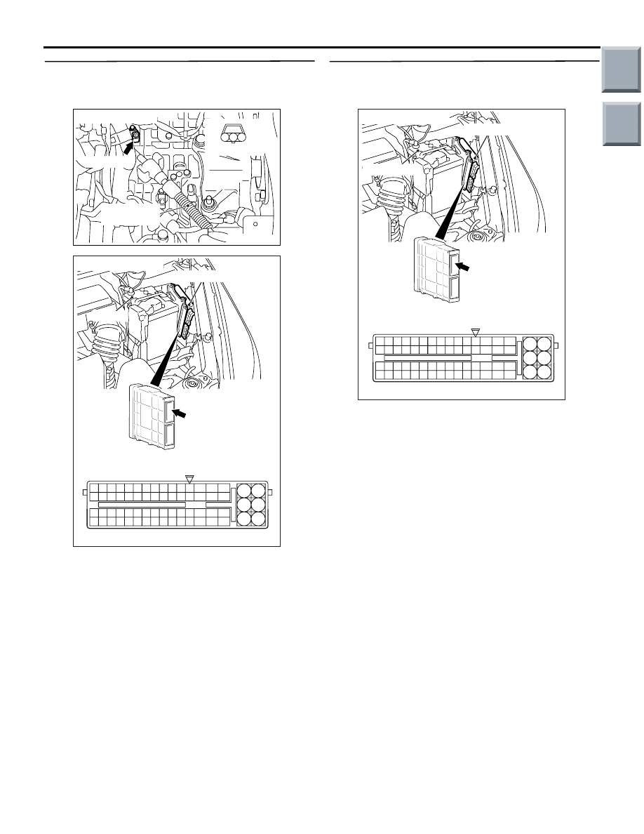
STEP 39. Check the harness between secondary 
speed sensor connector A-112 terminal No.2 and 
engine-CVT-ECU connector A-114 terminal No.45.

AC314193

Connector: A-112

AC

A-112 (B)

Transmission 
control cable

Harness side

1

2

3

AC403088AG

A-114

Connector: A-114

6

4

2

5

3

1

9

7

8

10

11

12

13

14

15

16

17

18

19

20

21

22

23

24

25

26

27

28

29

30

31

32

33

34

35

36

37

38

39

40

41

42

43

44

45

46

47

48

49

50

51

52

53

54

55

56

57

58

59

60

61

62

63

64

65

66

L

A-114 Harness side connector

Engine-CVT-ECU

Battery

(GR)

Check the output line for open circuit.

Q: Is the check result normal?

YES : 

Go to Step 28.

NO : 

Repair the wiring harness.

STEP 40. Measure the output wave pattern of the 
secondary speed sensor at engine-CVT-ECU 
connector A-114 (using an oscilloscope).

AC403088AF

A-114

Connector: A-114

6

4

2

5

3

1

9

7

8

10

11

12

13

14

15

16

17

18

19

20

21

22

23

24

25

26

27

28

29

30

31

32

33

34

35

36

37

38

39

40

41

42

43

44

45

46

47

48

49

50

51

52

53

54

55

56

57

58

59

60

61

62

63

64

65

66

L

A-114 Check connector (special tool)

Engine-CVT-ECU

Battery

(GR)

(1) Disconnect the engine-CVT-ECU connector, and 

connect the special tool Power plant ECU check 
harness (MB991987).

(2) Shift the selector lever to the D range.
(3) Accelerate the vehicle to approximately 50 km/h.
(4) Use the special tool Check connector to measure 

the voltage between engine-CVT-ECU connector 
A-114 terminal No.45 and earth.

OK: A wave pattern such as the one 
shown on 

P.23A-128

 (Check Procedure 

Using an Oscilloscope) should be output, 
and the maximum value should be 4.8 V 
or more and the minimum value should 
be 0.6 V or less. There should be no noise 
in the output wave pattern.

Q: Is the check result normal?

YES : 

Go to Step 41.

NO : 

Go to Step 42.

Main

Index

Group

TOC

TROUBLESHOOTING <CVT>

CVT

23A-52

STEP 41. Measure the output wave pattern of the 
primary speed sensor at engine-CVT-ECU 
connector A-114 (using an oscilloscope).

AC403088AF

A-114

Connector: A-114

6

4

2

5

3

1

9

7

8

10

11

12

13

14

15

16

17

18

19

20

21

22

23

24

25

26

27

28

29

30

31

32

33

34

35

36

37

38

39

40

41

42

43

44

45

46

47

48

49

50

51

52

53

54

55

56

57

58

59

60

61

62

63

64

65

66

L

A-114 Check connector (special tool)

Engine-CVT-ECU

Battery

(GR)

(1) Disconnect the engine-CVT-ECU connector, and 

connect the special tool Power plant ECU check 
harness (MB991987).

(2) Shift the selector lever to the D range.
(3) Accelerate the vehicle to approximately 50 km/h.
(4) Use the special tool Check connector to measure 

the voltage between engine-CVT-ECU connector 
A-114 terminal No.43 and earth.

OK: A wave pattern such as the one 
shown on 

P.23A-128

 (Check Procedure 

Using an Oscilloscope) should be output, 
and the maximum value should be 4.8 V 
or more and the minimum value should 
be 0.6 V or less. There should be no noise 
in the output wave pattern.

Q: Is the check result normal?

YES : . 

Go to Step 28.

NO : . 

Eliminate the cause of the noise.

STEP 42. Check the secondary speed sensor and 
then recheck the diagnosis code.
(1) Remove the secondary speed sensor. Wipe any 

metallic particles or dirt off the sensor tip.

(2) Install the secondary speed sensor and road test 

the vehicle.

(3) Check if the diagnosis code is set.

Q: Is diagnosis code set?

YES : 

Go to Step 43.

NO : 

The inspection is complete.

STEP 43. Replace the secondary speed sensor 
and then recheck the diagnosis code.
(1) Replace the secondary speed sensor. (Refer to 

P.23A-155

).

(2) Test drive the vehicle.
(3) Check if the diagnosis code is set.

Q: Is diagnosis code set?

YES : 

Go to Step 44.

NO : 

The inspection is complete.

STEP 44. Replace the CVT assembly and then 
recheck the diagnosis code.
(1) Replace the CVT assembly.
(2) Test drive the vehicle.
(3) Check if the diagnosis code is set.

Q: Is diagnosis code set?

YES : 

Eliminate the cause of the noise.

NO : 

The inspection is complete.

Main

Index

Group

TOC

TROUBLESHOOTING <CVT>

CVT

23A-53

Code No.24, 25 Secondary Speed Sensor System

ENGINE-
CVT-ECU

SECONDARY
SPEED SENSOR

Wire colour code
B : Black     LG : Light green     G : Green     L : Blue     W : White     Y : Yellow     SB : Sky blue
BR : Brown     O : Orange     GR : Gray     R : Red     P : Pink     V : Violet

Secondary Speed Sensor System Circuit

AC405422AB

OPERATION

The secondary speed sensor detects the secondary 
pulley speed at the transfer drive gear, and sends the 
information to the engine-CVT-ECU.

DIAGNOSIS CODE SET CONDITIONS

• If the secondary speed sensor signal is not 

detected while the vehicle is being driven (pri-
mary speed is 1,000 r/min), code No.24 will be 
set.

• If the ECU calculates the transmission ratio as 

2.5 or more and this condition lasts for 30 sec-
onds while the vehicle is being driven (neither pri-
mary nor secondary speeds are 0 r/min), code 
No.25 will be set.

PROBABLE CAUSES

• Malfunction of secondary speed sensor

• Malfunction of primary speed sensor

• Damaged harness wires and connectors

• Malfunction of the engine-CVT-ECU

• Malfunction of line pressure control solenoid 

valve

• Faulty CVT power train system

DIAGNOSIS PROCEDURE

STEP 1. Road test

Q: Can the vehicle be driven at the D range?

YES : 

Go to Step 2.

NO : 

Replace the CVT assembly.

Main

Index

Group

TOC

TROUBLESHOOTING <CVT>

CVT

23A-54

STEP 2. M.U.T.-III diagnosis code

Q: Is diagnosis code 31 set?

YES : 

Refer to diagnosis code 31: Line pressure 

control solenoid valve system 

P.23A-77

.

NO : 

Go to Step 3.

STEP 3. M.U.T.-III data list
Item 04: Secondary speed sensor (Refer to Data List 
Table 

P.23A-123

).

Q: Is the check result normal?

YES : 

Go to Step 25.

NO : 

Go to Step 4.

STEP 4. Connector check: A-112 secondary 
speed sensor connector.

AC314193

Connector: A-112

AC

A-112 (B)

Transmission 
control cable

Harness side

1

2

3

Check for the contact with terminals.

Q: Is the check result normal?

YES : 

Go to Step 5.

NO : 

Repair the defective connector.

STEP 5. Measure the resistance at secondary 
speed sensor connector A-112.

AC314193

Connector: A-112

AC

A-112 (B)

Transmission 
control cable

Harness side

1

2

3

Disconnect the connector, and measure the resist-
ance between terminal 1 and earth at the wiring har-
ness side.

OK: 2 

 or less

Q: Is the check result normal?

YES : 

Go to Step 11.

NO : 

Go to Step 6.

STEP 6. Measure the voltage at engine-CVT-ECU 
connector A-114.
(1) Connect secondary speed sensor connector 

A-112.

AC403088AF

A-114

Connector: A-114

6

4

2

5

3

1

9

7

8

10

11

12

13

14

15

16

17

18

19

20

21

22

23

24

25

26

27

28

29

30

31

32

33

34

35

36

37

38

39

40

41

42

43

44

45

46

47

48

49

50

51

52

53

54

55

56

57

58

59

60

61

62

63

64

65

66

L

A-114 Check connector (special tool)

Engine-CVT-ECU

Battery

(GR)

(2) Disconnect the engine-CVT-ECU connector, and 

connect the special tool Power plant ECU check 
harness (MB991987).

(3) Turn the ignition switch to the ON position.
(4) Use the special tool Check connector to measure 

the voltage between engine-CVT-ECU connector 
A-114 terminal No.60 and earth.

OK: 0.5 V or less

Q: Is the check result normal?

YES : 

Go to Step 9.

NO : 

Go to Step 7.

Main

Index

Group

TOC


Content   ..  175  176  177  178   ..