Mitsubishi Colt Ralliart. Manual - part 116
EXHAUST PIPE AND MAIN MUFFLER
INTAKE AND EXHAUST
15-20
REMOVAL SERVICE POINT
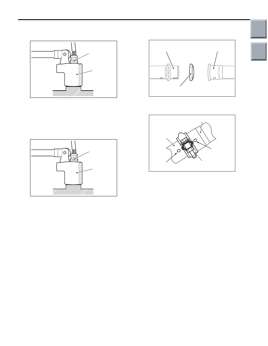
<<A>> OXYGEN SENSOR REMOVAL
AC301966
AB
MB991953
Oxygen sensor
Remove the connection and clamp of oxygen sensor
connector, and then use special tool oxygen sensor
wrench (MB991953) to remove the oxygen sensor.
INSTALLATION SERVICE POINTS
>>A<< OXYGEN SENSOR INSTALLATION
AC301966
AB
MB991953
Oxygen sensor
1. Tighten the oxygen sensor to the specified torque
by using special tool oxygen sensor wrench
(MB991953).
Tightening torque:50
± 10 N⋅m
2. Connect the oxygen sensor connector and install
the connector bracket.
>>B<< EXHAUST PIPE GASKET /
EXHAUST PIPE CLAMP INSTALLATION
AC207712 AC
Exhaust main muffler
Centre exhaust pipe
Exhaust pipe gasket
1. Install the exhaust pipe gasket in the direction
shown in the illustration.
AC207713 AD
AC207713
Exhaust main muffler
Exhaust
centre pipe
Concave
part
Concave
part
Exhaust pipe
clamp
2. Confirm that the exhaust main muffler and the
concave parts at the rear side of the centre
exhaust pipe are located as shown in the
illustration. Install the exhaust pipe clamp so that
its mounting bolts are in the direction shown in the
illustration.
Main
Index
Group
TOC