Mitsubishi Colt Ralliart. Manual - part 104
THROTTLE BODY ASSEMBLY
MULTIPORT FUEL INJECTION (MPI) <4A9>
13A-370
THROTTLE BODY ASSEMBLY
REMOVAL AND INSTALLATION
M1131007701495
CAUTION
• When the throttle body assembly replacement is performed, use the M.U.T.-III to initialize the
learning value (Refer to GROUP 00, Precautions Before Service
− Initialization Procedure for
Learning Value in MPI Engine
).
• Do not loosen the fixing screws for the resin cover of throttle body assembly. If the screws are
loosened, the sensor incorporated in the resin cover becomes misaligned and the throttle body
can not work normally.
Pre-removal Operation
• Engine Cover Removal (Refer to GROUP 11A, Camshaft
• Engine Coolant Draining (Refer to GROUP 14, On-vehicle
Service
− Engine Coolant Replacement
).
• Air Cleaner Assembly Removal (Refer to GROUP 15, Air
Cleaner
).
Post-installation Operation
• Air Cleaner Assembly Installation (Refer to GROUP 15,
Air Cleaner
).
• Engine Coolant Supplying (Refer to GROUP 14, On-vehi-
cle Service
− Engine Coolant Replacement
).
• Engine Cover Installation (Refer to GROUP 11A, Cam-
shaft
AC405190 AB
2
4
5
6
1
6.0 ± 0.5 N·m
N
3
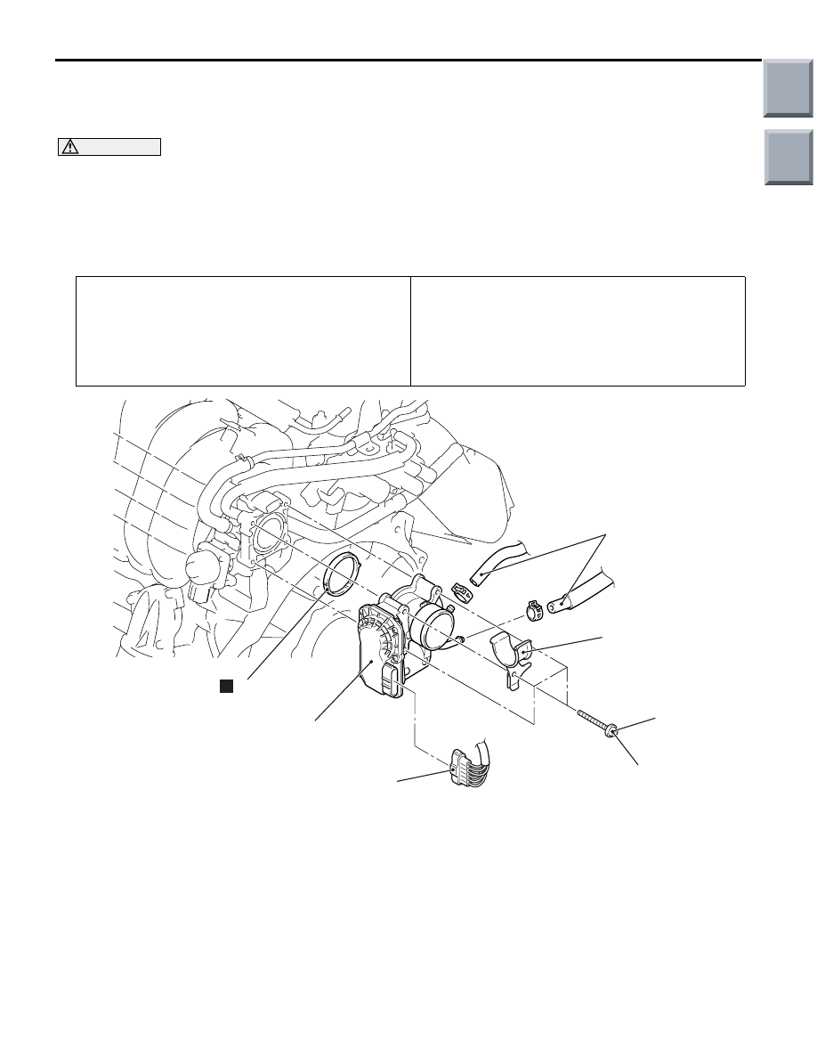
Removal steps
>>
C
<< •
Initialization (Installation only)
1.
Electronic control throttle valve
connector
2.
Throttle body water hose
connection
>>
B
<< 3.
Screw
4.
Radiator upper hose clamp
5.
Throttle body assembly
>>
A
<< 6.
Throttle body gasket
Removal steps (Continued)
Main
Index
Group
TOC