Mitsubishi Colt Ralliart. Manual - part 81


  Index      Mitsubishi     Mitsubishi Colt Ralliart - service repair manual


Search            


Content   ..  79  80  81  82   ..


Mitsubishi Colt Ralliart. Manual - part 81


TROUBLESHOOTING

MULTIPORT FUEL INJECTION (MPI) <4A9>

13A-278

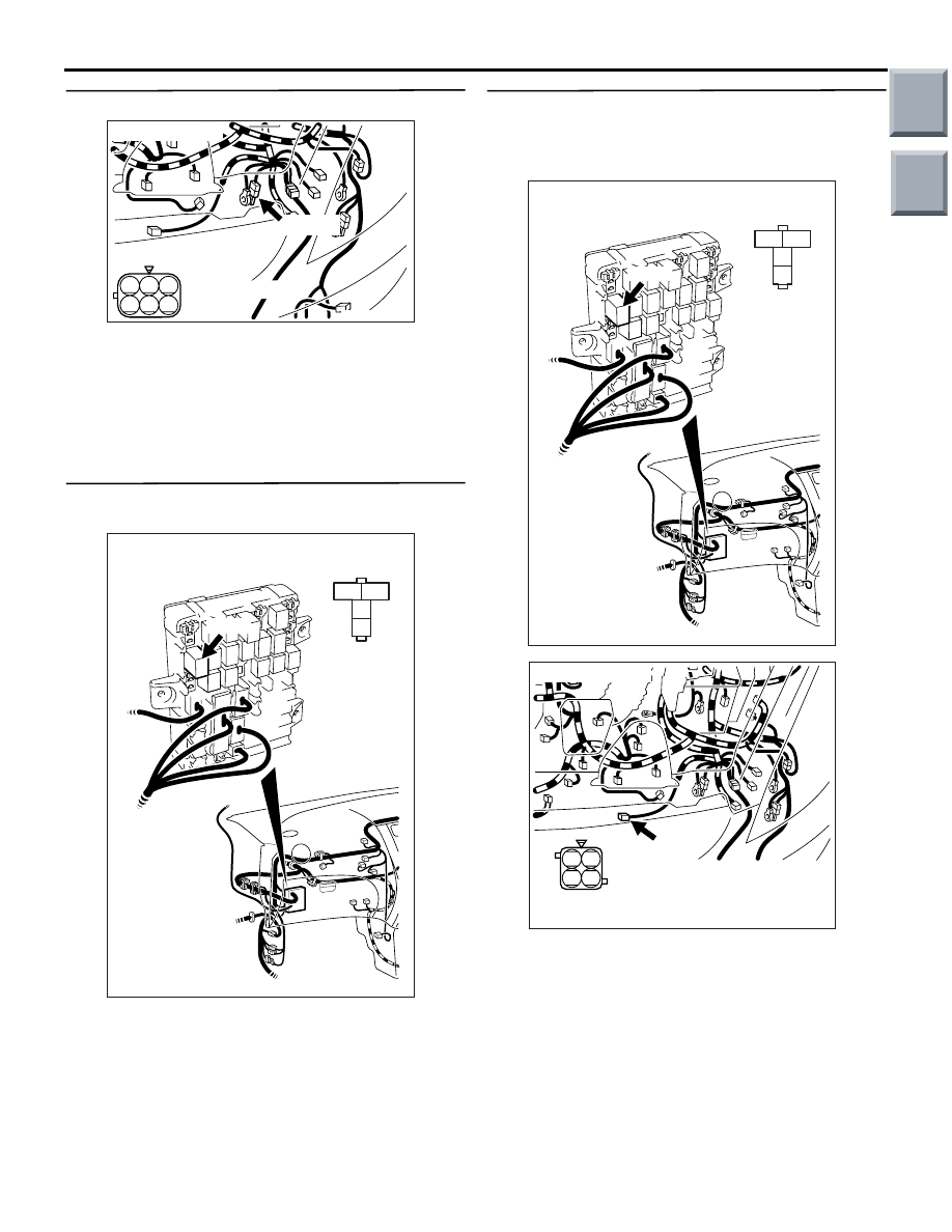
STEP 7. Connector check: A-31 earth connector

Q: Is the check result normal?

YES : 

Check and repair harness between A-20 

(terminal No. 2) cooling fan motor connector 
and A-31 (terminal No. 2) earth connector.

• Check earthing line for damage.

NO : 

Repair or replace the connector.

STEP 8. Connector check: B-114 cooling fan 
control relay connector

Q: Is the check result normal?

YES : 

Go to Step 9 .

NO : 

Repair or replace the connector.

STEP 9. Check harness between B-114 (terminal 
No. 4) cooling fan control relay connector and 
A-20 (terminal No. 1) cooling fan motor 
connector.

NOTE: Before checking harness, check intermediate 
connector B-109, and repair if necessary.

• Check power supply line for damage.

Q: Is the check result normal?

YES : 

Go to Step 10 .

NO : 

Repair the damaged harness wire.

AK402208

3

2 1

6

5 4

Connector: A-31

A-31 (G)

AC

A-31 Harness side
connector

AK402058

3

2

1

4

AC

B-114
J/B side 
connector

Connector: B-114

J/B (front side)

B-114

AK402058

3

2

1

4

AC

B-114
J/B side 
connector

Connector: B-114

J/B (front side)

B-114

AK402059

2 1

4 3

AC

A-20 Harness
side connector

A-20

Connector: A-20

Main

Index

Group

TOC

TROUBLESHOOTING

MULTIPORT FUEL INJECTION (MPI) <4A9>

13A-279

STEP 10. Check harness between battery and 
B-114 (terminal No. 3) cooling fan control relay 
connector.

NOTE: Before checking harness, check intermediate 
connector B-108, and repair if necessary.

• Check power supply line for damage.

Q: Is the check result normal?

YES : 

Go to Step 11 .

NO : 

Repair the damaged harness wire.

STEP 11. Check the trouble symptoms.

Q: Does trouble symptom persist?

YES : 

Replace engine-ECU <M/T> or 

engine-CVT-ECU <CVT>.

NO : 

Intermittent malfunction (Refer to GROUP 
00 

− How to Use 

Troubleshooting/Inspection Service Points 

− 

How to Cope with Intermittent Malfunctions 

P.00-13

).

AK402058

3

2

1

4

AC

B-114
J/B side 
connector

Connector: B-114

J/B (front side)

B-114

Main

Index

Group

TOC

TROUBLESHOOTING

MULTIPORT FUEL INJECTION (MPI) <4A9>

13A-280

Inspection Procedure 22: Poor A/C performance

COMMENT ON TROUBLE SYMPTOM

• Failure is possibly caused by short /overcharged 

A/C refrigerant, failed A/C control system, failed 
fan control system or other faults.

PROBABLE CAUSES

• Short or overcharged A/C refrigerant

• Failed A/C compressor relay

• Failed cooling fan control relay

• Failed A/C-ECU

• Failed engine-ECU <M/T> or engine-CVT-ECU 

<CVT>

DIAGNOSIS PROCEDURE

STEP 1. M.U.T.-III diagnosis code

Q: Is the diagnosis code set?

YES : 

Inspection chart for diagnosis code (Refer 

to 

P.13A-20

).

NO : 

Go to Step 2 .

STEP 2. A/C compressor magnet clutch 
operation check.

• Engine: Idling

• A/C set temperature:

Maximum Cool when temperature in cabin is 

25

°C or more

Maximum Hot when temperature in cabin is 25

°C 

or less

OK:

Magnet clutch active (when A/C is ON)
Magnet clutch inactive (when A/C is OFF)

Q: Is the check result normal? 

YES : 

Go to Step 4 .

NO : 

Go to Step 3 .

STEP 3. M.U.T.-III data list

• Item 49: A/C relay

a. Engine: Idling
b. A/C set temperature:

Maximum Cool when temperature in cabin is 

25

°C or more

Maximum Hot when temperature in cabin is 

25

°C or less

OK: 

ON (when A/C is ON)
OFF (when A/C is OFF)

Q: Is the check result normal?

YES : 

Check A/C system (Refer to GROUP 55A 

− 

Check Chart For Diagnosis Code 

P.55A-5

).

NO : 

Check A/C compressor relay (Refer to 
Inspection Procedure 26 

P.13A-310

).

STEP 4. M.U.T.-III actuator test

• Refer to Actuator Test Reference Table 

P.13A-341

.

a. Item 20: Cooling fan motor

Q: Are the check results normal?

YES : 

Check charged amount of A/C refrigerant 

(Refer to GROUP 55 

− On-vehicle Service − 

Check The Refrigerant Level 

P.55A-50

).

NO : 

Check fan control relay system (Refer to 
Inspection Procedure 25 

P.13A-302

).

Main

Index

Group

TOC

TROUBLESHOOTING

MULTIPORT FUEL INJECTION (MPI) <4A9>

13A-281

Inspection Procedure 23: Engine-ECU <M/T> or engine-CVT-ECU <CVT> power supply, engine control 
relay, ignition switch-IG1 system

AK402702

R

92 93 94 95969798

77 78 79 808182838485868788899091

99

100

107 108 109 110 111112113114115116117118119120121
122 123 124 125126127128129130131132133134135136

101102103104105106

71 72

73 74

75 76

3

1

2

4

1 2 3
4 5 6

B-141

B-106

A-08

R

IG2

ST

LOCK

ACC

IG1

16

1

20A

38

7.5A

Fusible link

Ignition switch

3

2

J/B

122

75

2

76

B

B

3

B-110

B-112

B-112

B-112

B-108

B-129

82

Engine 
control 
relay

3

1

1

4

2

107

Battery
backup

92

19

23

6

77

Power
source

9

R

R-B

B-O

L-B

G

R

R

Power Supply And Ignition Switch-IG Circuit

10

10A

Engine-ECU <M/T> or
engine-CVT-ECU <CVT>

A-31
 J/C

A-30
 J/C

AC

GND

GND

Wire colour code
B: Black  LG: Light green  G: Green  L: Blue  W: White  Y: Yellow  SB: Sky blue  BR: Brown  O: Orange  GR: Gray
R: Red  P: Pink  V: Violet  Pu: Purple

Main

Index

Group

TOC


Content   ..  79  80  81  82   ..