Mitsubishi Colt Ralliart. Manual - part 53


  Index      Mitsubishi     Mitsubishi Colt Ralliart - service repair manual


Search            


Content   ..  51  52  53  54   ..


Mitsubishi Colt Ralliart. Manual - part 53


TROUBLESHOOTING

MULTIPORT FUEL INJECTION (MPI) <4A9>

13A-166

Code No. P0513: Immobilizer Malfunction
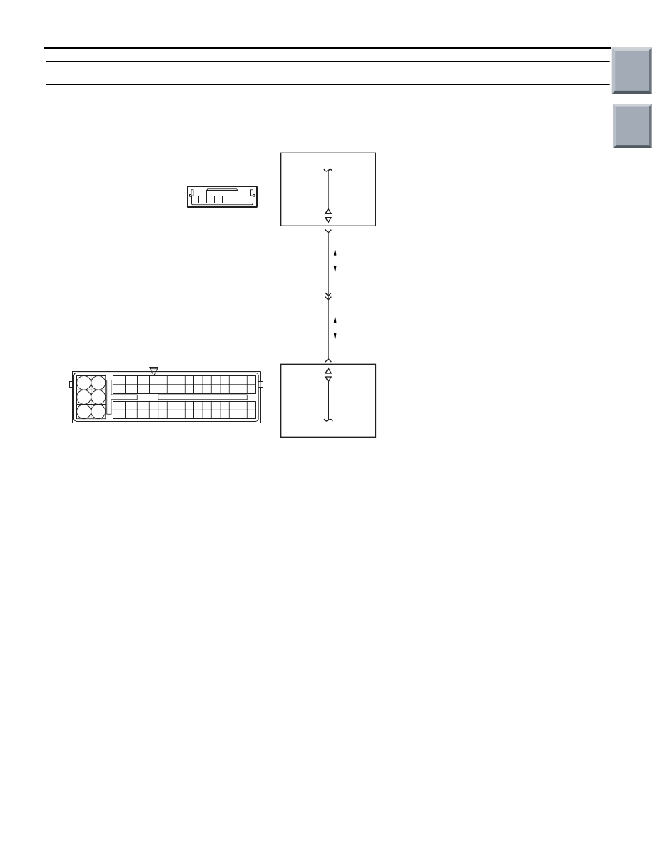
OPERATION

• The signals are sent and received between 

engine-ECU <M/T> or engine-CVT-ECU <CVT> 
(terminal No. 120) and immobilizer-ECU (terminal 
No. 3).

FUNCTION

• The engine-ECU <M/T> or engine-CVT-ECU 

<CVT> sends or receives the control signals to or 
from immobilizer-ECU to certify the ignition key.

NOTE: 

.

If the registered ignition keys are close each 
other when starting the engine, radio interfer-
ence may cause this code to be displayed.

This code may be displayed when registering 
the key encrypted code.

TROUBLE JUDGMENT

Check Condition

• Ignition switch is in "ON" position.

Judgment Criterion

• The communication error between engine-ECU 

<M/T> or engine-CVT-ECU <CVT> and the 
immobilizer-ECU for 4 seconds.

PROBABLE CAUSES

• Open/short circuit in immobilizer system circuit or 

loose connector contact

• Failed immobilizer-ECU

• Failed engine-ECU <M/T> or engine-CVT-ECU 

<CVT>

AK503589

R

92 93 94 95969798

77 78 79 808182838485868788899091

99

100

107 108 109 110 111112113114115116117118119120121

122 123 124 125126127128129130131132133134135136

101102103104105106

71 72

73 74

75 76

1 2 3 4 5 6 7 8

AC

Immobilizer-ECU Circuit

B-49

A-08

Engine-ECU <M/T> or
engine-CVT-ECU <CVT>

Immobilizer-ECU

Wire clolour code
B: Black  LG: Light green  G: Green  L: Blue  W: White  Y: Yellow  SB: Sky blue  BR: Brown  O: Orange  GR: Gray  
R: Red  P: Pink  V: Violet

  PU: Purple

120

10

B-40

BR

BR

3

Main

Index

Group

TOC

TROUBLESHOOTING

MULTIPORT FUEL INJECTION (MPI) <4A9>

13A-167

DIAGNOSIS PROCEDURE

STEP 1. Connector check: B-49 immobilizer-ECU 
connector and A-08 engine-ECU connector or 
engine-CVT-ECU connector.

Q: Is the check result normal? 

YES : 

Go to Step 2 .

NO : 

Repair or replace.

STEP 2. Check harness between B-49 (terminal 
No. 3) immobilizer-ECU connector and A-08 
(terminal No. 120) engine-ECU connector or 
engine-CVT-ECU connector.

NOTE: Before checking harness, check intermediate 
connector B-40, and repair if necessary.

• Check output line for open/short circuit and dam-

age.

Q: Is the check result normal? 

YES : 

Go to Step 3 .

NO : 

Repair.

STEP 3. Check the trouble symptoms.

Q: Is the check result normal? 

YES : 

Go to Step 4 .

NO : 

Intermittent malfunction (Refer to GROUP 
00 

− How to Use Troubleshooting/Inspection 

Service Points 

− How to Cope with 

Intermittent Malfunctions 

P.00-13

).

AK503591

8 7 6 5 4 3 2 1

B-49

AB

Connectr: B-49

Harness side

connector

AK402725

77

78

79

80

81

82

83

84

92

93

94

95

96

97

98

99

85

86

87

88

89

90

91

100

101

102

103

104

105

106

115

116

117

118

119

120

121

107

108

109

110

111

112

113

114

130

131

132

133

134

135

136

122

123

124

125

126

127

128

129

72 71

74 73

76 75

R

AG

A-08

Connector: 

A-08

Harness side connector

Battery

Engine-ECU <M/T> or
engine-CVT-ECU <CVT>

Main

Index

Group

TOC

TROUBLESHOOTING

MULTIPORT FUEL INJECTION (MPI) <4A9>

13A-168

STEP 4. After replacing the immobilizer-ECU, 
re-check the trouble symptoms.

Q: Is the check result normal? 

YES : 

Replace engine-ECU <M/T> or 

engine-CVT-ECU <CVT>.

NO : 

Check end.

Code No. P0603: EEP ROM MALFUNCTION

FUNCTION

• To check whether the information such as the idle 

learned value and so on is stored in the memory 
of engine-ECU <M/T> or engine-CVT-ECU 
<CVT>.

TROUBLE JUDGMENT

Check Condition

• Ignition switch is in ON position.

Judgement Criterion

• The latest learned data that was flashed while the 

ignition switch was in OFF position are not stored 
correctly.

PROBABLE CAUSE

• Failed the engine-ECU <M/T> or 

engine-CVT-ECU <CVT>

DIAGNOSIS

STEP 1. M.U.T.-III diagnosis code 

• Reconfirmation of diagnosis code.

Q: Is the check result normal?

YES : 

Replace engine-ECU <M/T> or 

engine-CVT-ECU <CVT>.

NO : 

Intermittent malfunction (Refer to GROUP 
00 

− How to Use 

Troubleshooting/Inspection Service Points 

− 

How to Cope with Intermittent Malfunctions 

P.00-13

).

Code No. P0606: Microcomputer Malfunction System

FUNCTION

• The engine-ECU <M/T> or engine-CVT-ECU 

<CVT> check whether the microcomputer, which 
performs the drive control of the throttle valve, is 
normal.

TROUBLE JUDGMENT

Check Condition

• Ignition switch is ON position.

Judgment Criteria

• Battery voltage is more than 6.3 V <M/T>.

or

• Main microcomputer reference voltage is abnor-

mal.

PROBABLE CAUSE

• Failed engine-ECU <M/T> or engine-CVT-ECU 

<CVT>

DIAGNOSIS

STEP 1. M.U.T.-III diagnosis code

• Reconfirmation of diagnosis code.

Q: Is the diagnosis code set?

YES : 

Replace engine-ECU <M/T> or 

engine-CVT-ECU <CVT>.

NO : 

Intermittent malfunction (Refer to GROUP 
00 

− How to Use 

Troubleshooting/Inspection Service Points 

− 

How to Cope with Intermittent Malfunctions 

P.00-13

).

Main

Index

Group

TOC

TROUBLESHOOTING

MULTIPORT FUEL INJECTION (MPI) <4A9>

13A-169

Code No. P0622: Alternator FR Terminal System

OPERATION

• The energized state of the alternator field coil is 

inputted from the alternator (terminal No. 4) to the 
engine-ECU <M/T> or engine-CVT-ECU <CVT> 
(terminal No. 65).

FUNCTION

• A signal of the power supply duty ratio for the 

alternator field coil is inputted to the engine-ECU 
<M/T> or engine-CVT-ECU <CVT>.

• In response to the signal, the engine-ECU <M/T> 

or engine-CVT-ECU <CVT> detects the alterna-
tor output current and controls the idling speed 
according to the output current (electric load).

TROUBLE JUDGMENT

Check Conditions

• After engine starts <M/T>

• Engine speed is 50 r/min or higher <CVT>.

Judgment Criterion

• Input voltage from the alternator FR terminal has 

continued to be system voltage for 20 seconds.

PROBABLE CAUSES

• Failed alternator

• Open/short circuit in alternator FR terminal circuit 

or loose connector contact

• Failed engine-ECU <M/T> or engine-CVT-ECU 

<CVT>

AK402692

1

2

3 4

19

21

20

18

17

16

15

14

1213

11

8 9

L

10

37
52 53 54 555657585960616263646566

38 39 404142434445464748495051

22 23 24 252627282930313233343536

7

5

3

1

6

4

2

Engine-ECU <M/T> or
engine-CVT-ECU <CVT>

Alternator

Y-B

IC voltage
regulator

65

Alternator Circuit

      A-131
(MU802046)

A-114

AD

Wire colour code
B: Black  LG: Light green  G: Green  L: Blue  W: White  Y: Yellow  SB: Sky blue  BR: Brown  O: Orange  GR: Gray
R: Red  P: Pink  V: Violet  Pu: Purple

Main

Index

Group

TOC


Content   ..  51  52  53  54   ..