Mitsubishi Canter (FE, FG). Manual - part 32


  Index      Mitsubishi     Mitsubishi Canter (FE, FG) - service manual 2013 year


Search            


Content   ..  30  31  32  33   ..


Mitsubishi Canter (FE, FG). Manual - part 32


128

7 Construction of bodies 

7.6 BlueTec

®

 system

MITSUBISHI FUSO body/equipment mounting directives for FE, FG  Issue date: 06. 07. 2012

!

 Only print out complete sections from the current version

i

7.6 BlueTec

® 

system

7.6.1

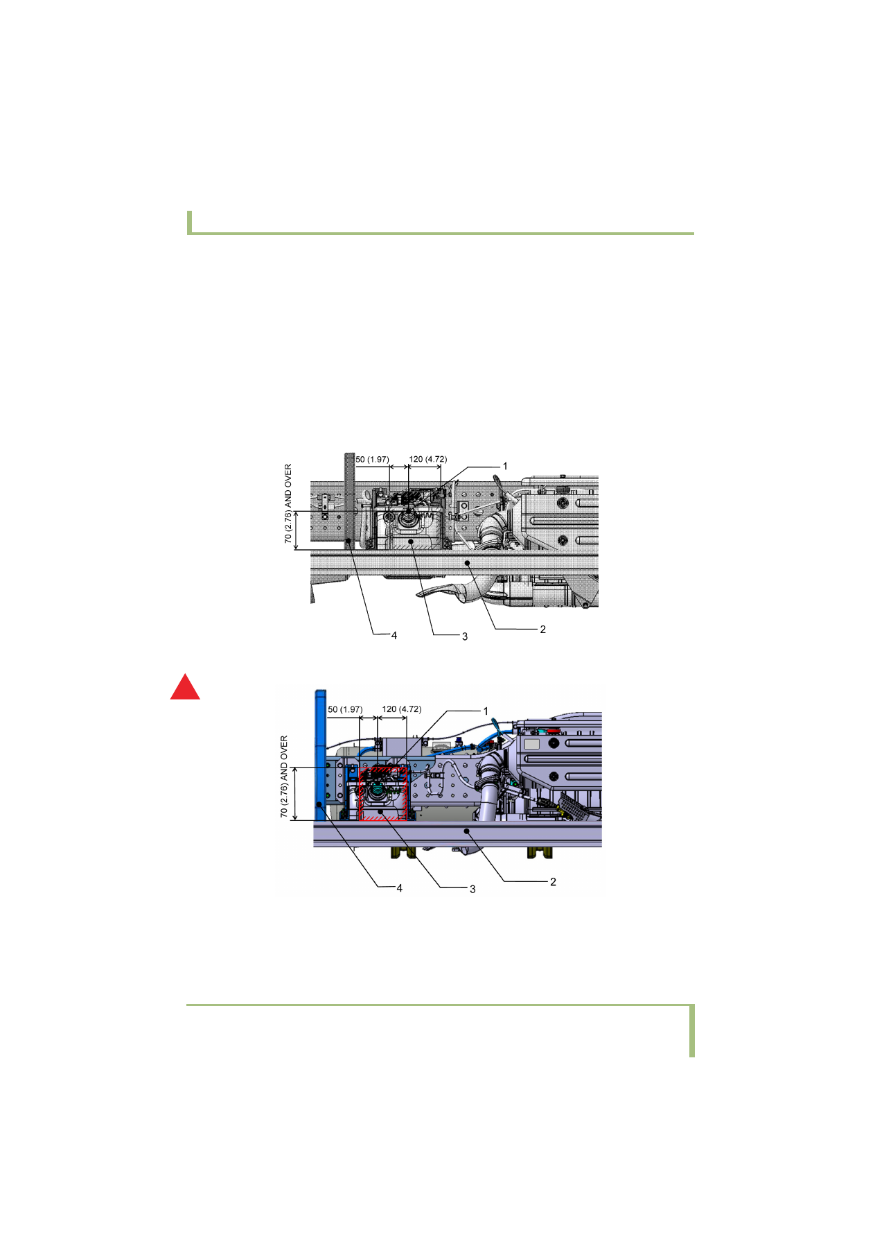
Installing a side guard and other parts around the DEF tank

• Care is required when installing a side guard around the DEF tank. Do not let the side guard and its mounting 

bracket(s) hide the filler cap of the tank and interfere with refilling the tank with DEF. Be sure to open up 
sufficient space around the cap to allow a filler nozzle of DEF to be inserted; typical dimensions of filler guns 
are shown in the figures below.

• Allow a clearance of at least 25 mm {0.98 in.} between the side guard, mud guard, etc. installed around the 

DEF tank and the following parts of the DEF tank: front end, rear end, and outer side.

• Avoid directly attaching parts to any of the DEF tank brackets.
• Maintain sufficient free space to insert DEF filler nozzle. (shaded area)

<FE>

Fig.1

<FG>

Fig.2

A

1

Cap

2

Side  guard

3

DEF  tank

4

Side guard mounting stay

129

7 Construction of bodies 

7.6 BlueTec

®

 system

MITSUBISHI FUSO body/equipment mounting directives for FE, FG  Issue date: 06. 07. 2012

!

 Only print out complete sections from the current version

i

DEF filler nozzle - Examples

180 {7.09}

200 {7.87}

100 {3.94}

60 {2.36}

19 {0.75}

160 {6.30}

unit: mm {in.}

Fig. 3

130

7 Construction of bodies 

7.6 BlueTec

®

 system

MITSUBISHI FUSO body/equipment mounting directives for FE, FG  Issue date: 06. 07. 2012

!

 Only print out complete sections from the current version

i

7.6.2

DEF tank and connection piping

The DEF tank with a DEF pump module inside, the 
dosing module, and their connection piping are all 
installed conforming to the relevant exhaust gas 
control requirements. It is prohibited to relocate these 
components and change their piping when mounting 
the body or equipment.

<FE>

Fig.1

<FG>

Fig.2

Fig.3

There are DEF


hose connecting ports near the points 

marked  (2 places in total). After any operation 
including mounting the body or equipment near these 
areas, visually check that the clamps of the coupling 
connector are fully closed regardless of whether you 
touch the piping or not.

A

1

Dosing module

2

SCR  muffler

3

DEF  tank

!

Applying undue force to hoses may damage their 
connections. Do not pull on hoses or step on their 
connections.

131

7 Construction of bodies 

7.6 BlueTec

®

 system

MITSUBISHI FUSO body/equipment mounting directives for FE, FG  Issue date: 06. 07. 2012

!

 Only print out complete sections from the current version

i

7.6.3

Precautions for electric welding

If electric welding is performed while the electric 
wiring for the pump module of the BlueTec

®

 system is 

still connected, the internal electric circuits on the 
module could be damaged. Be sure to disconnect the 
module's electric wiring connector as follows before 
starting electric welding:

• Turn the starter switch to "OFF".
• Leave the starter switch in the "OFF" position for at 

least 1 minute. (This is necessary for the after-
running processing.)

• Disconnect the wiring connector on the pump 

module side.

• Be sure to ground the welder close to the welding 

area.

When reconnecting the connector after completing 
welding, confirm that the starter switch is in the "OFF" 
position.

!

Do not divide any power supply from an existing 
fuse.

Especially the BlueTec

®

 system will not work if its 

fuse has blown. In winter and cold areas, the 
system consumes more electric power for its 
heater to prevent freezing. Never branch power for 
another electric device from the fuse.


Content   ..  30  31  32  33   ..