Mitsubishi Canter (FE, FG). Manual - part 12
48
4 Technical threshold values for planning
4.5 Air deflectors
MITSUBISHI FUSO body/equipment mounting directives for FE, FG Issue date: 06. 07. 2012
!
Only print out complete sections from the current version
i
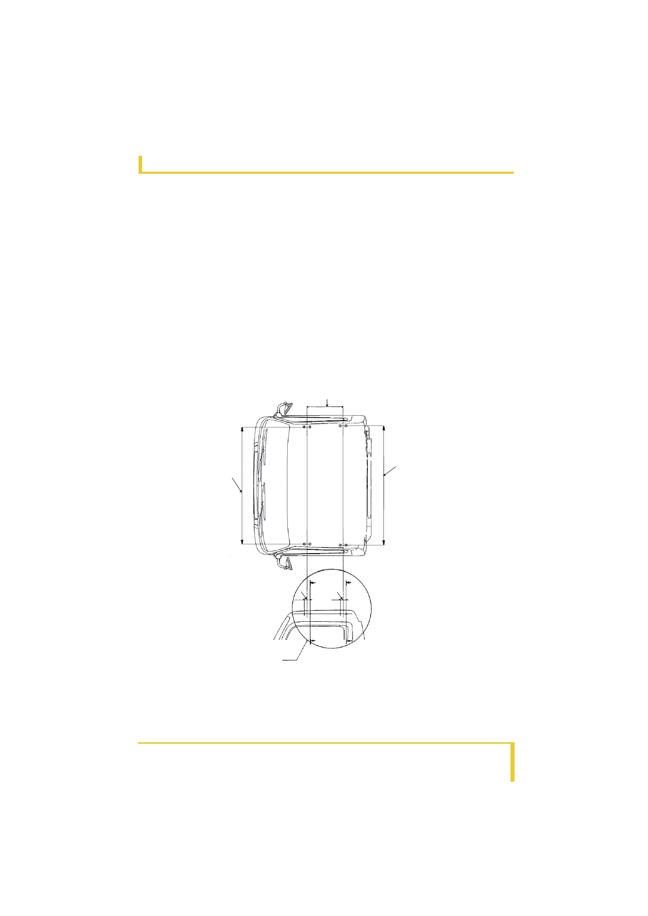
4.5 Air deflectors
4.5.1
Attaching the roof deck
Roof
• When attaching externally mounted parts such as
an air deflector onto the roof, use only the
threaded factory mounting holes provided on the
roof.
• The total weight of externally mounted parts
attached to the roof cannot exceed 50 kg {110 lb}.
(See Figs. 1, 2 and 4.)
Cautions
• Use nickel-chrome plated stainless steel bolts and
washers.
• Take special care to prevent the body from
becoming scratched when attaching externally
mounted parts.
• Insert packing between externally mounted parts
and the body to prevent rusting. Use packing made
of EPDM rubber to prevent ozone cracking.
• After attaching externally mounted parts, coat the
entire periphery of the mounting bolts with sealer.
• A top coat of paint must be applied to externally
mounted parts before attaching to the roof. (See
Fig. 3.)
Fig. 1
4
1
2
6
7
5
2
1
3
3
1
Section A-A
2
Section B-B
3
80 mm {3.15 in.}
4
Detail C
5
1664 mm {65.5 in.}
6
1694 mm {66.7 in.}
7
500 mm {19.7 in.}