Mitsubishi 380. Manual - part 949


  Index      Mitsubishi     Mitsubishi 380 - service repair manual 2005 year


Search            


Content   ..  947  948  949  950   ..


Mitsubishi 380. Manual - part 949


ANTI-LOCK BRAKING SYSTEM (ABS) DIAGNOSIS

ANTI-LOCK BRAKING SYSTEM (ABS)

35B-21

Q: Is the harness wire between ABS-ECU connector A-02 

(terminal 5, 16) and wheel speed sensor <front: LH> 
connector A-04 (terminal 1, 2) damaged?
YES : 
Repair the wiring harness. Then go to Step 16.
NO :  Go to Step 14.

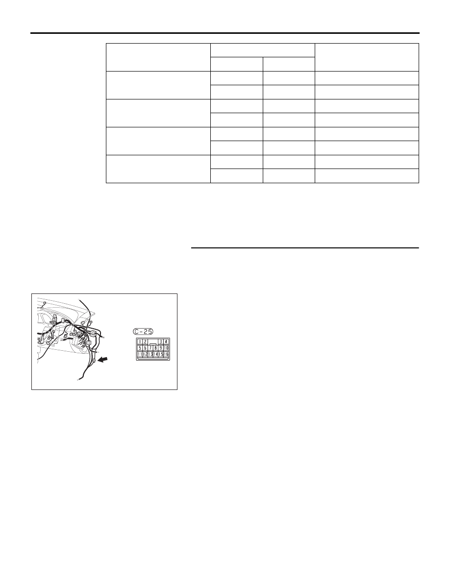
STEP 10. Check ABS-ECU connector A-02, intermediate 
connector C-25 and wheel speed sensor <rear: RH> 
connector D-30 for loose, corroded or damaged terminals, 
or terminals pushed back in the connector.
Q: Are ABS-ECU connector A-02, intermediate connector 

C-25 and wheel speed sensor <rear: RH> connector 
D-30 damaged?
YES : 
Repair or replace the damaged component(s). Refer 

to GROUP 00E, Harness Connector Inspection 

P.00E-2

. Then go to Step 16.

NO :  Go to Step 11.

              SIGNAL

   TERMINAL  NO.

  NORMAL CONDITION

 ABS (A-02)

   SENSOR

FR wheel speed sensor  
(A-01)

9

2

Less than 2 ohms

10

1

Less than 2 ohms

RR wheel speed sensor  
(D-30)

8

1

Less than 2 ohms

19

2

Less than 2 ohms

FL wheel speed sensor   
(A-04)

16

2

Less than 2 ohms

5

1

Less than 2 ohms

RL wheel speed sensor   
(D-31)

6

1

Less than 2 ohms

17

2

Less than 2 ohms

35DB033A

CONNECTOR: C-25

C-25

ANTI-LOCK BRAKING SYSTEM (ABS) DIAGNOSIS

ANTI-LOCK BRAKING SYSTEM (ABS)

35B-22

STEP 11. Check the harness wires and continuity 
resistance  between ABS-ECU connector A-02 (terminal 8, 
19) and wheel speed sensor <rear: RH> connector D-30 
(terminal 1, 2). (see figure and table below).

NOTE: The special tool (Inspection test harness) MB991219 
for connector pin contact pressure should be used. The test 
probe should never be forcibly inserted, as it may cause a 
defective contact.

Q: Is the harness wire between ABS-ECU connector A-02 

(terminal 8, 19) and wheel speed sensor <rear: RH> 
connector D-30 (terminal 1, 2) damaged?
YES : 
Repair the wiring harness. Then go to Step 16.
NO :  Go to Step 14.

              SIGNAL

   TERMINAL  NO.

  NORMAL CONDITION

 ABS (A-02)

   SENSOR

FR wheel speed sensor  
(A-01)

9

2

Less than 2 ohms

10

1

Less than 2 ohms

RR wheel speed sensor  
(D-30)

8

1

Less than 2 ohms

19

2

Less than 2 ohms

FL wheel speed sensor   
(A-04)

16

2

Less than 2 ohms

5

1

Less than 2 ohms

RL wheel speed sensor   
(D-31)

6

1

Less than 2 ohms

17

2

Less than 2 ohms

ABS-ECU
 CONNECTOR
 (A-02)

Supply

Signal

WHEEL SPEED
    SENSOR

Wheel speed 
sensor connectors:
A-04,  A-01,  D-31,  D-30

Terminals:
 5, 10, 17, 19

35DB123A

Terminals:
 16, 9, 6, 8

ANTI-LOCK BRAKING SYSTEM (ABS) DIAGNOSIS

ANTI-LOCK BRAKING SYSTEM (ABS)

35B-23

STEP 12. Check ABS-ECU connector A-02, intermediate 
connector C-25 and wheel speed sensor <rear: LH> 
connector D-31 for loose, corroded or damaged terminals, 
or terminals pushed back in the connector.

Q: Are ABS-ECU connector A-02, intermediate connector 

C-25 and wheel speed sensor <rear: LH> connector 
D-31 damaged?
YES : 
Repair or replace the damaged component(s). Refer 

to GROUP 00E, Harness Connector Inspection 

P.00E-2

. Then go to Step 16.

NO :  Go to Step 13..

STEP 13. Check the harness wires and continuity 
resistance between ABS-ECU connector A-02 (terminal 6, 
17) and wheel speed sensor <rear: LH> connector D-31 
(terminal 1, 2). (see figure and table below).

NOTE: The special tool (Inspection test harness) MB991219 
for connector pin contact pressure should be used. The test 
probe should never be forcibly inserted, as it may cause a 
defective contact.

35DB033A

CONNECTOR: C-25

C-25

ABS-ECU
 CONNECTOR
 (A-02)

Supply

Signal

WHEEL SPEED
    SENSOR

Wheel speed 
sensor connectors:
A-04,  A-01,  D-31,  D-30

Terminals:
 5, 10, 17, 19

35DB123A

Terminals:
 16, 9, 6, 8

ANTI-LOCK BRAKING SYSTEM (ABS) DIAGNOSIS

ANTI-LOCK BRAKING SYSTEM (ABS)

35B-24

Q: Is the harness wire between ABS-ECU connector A-02 ( 

terminal 6, 17) and wheel speed sensor <rear: LH> 
connector D-31 (terminal 1, 2) damaged?
YES : 
Repair the wiring harness. Then go to Step 16.
NO :  Go to Step 14.

STEP 14. Inspect the wheel speed sensor.
Check the wheel speed sensor relevant to the DTC code. For 
the applicable inspection procedure, refer to 

P.35B-96

.

• When DTC code C1200 is set: Front right wheel speed sen-

sor

• When DTC code C1205 is set: Front left wheel speed sen-

sor

• When DTC code C1210 is set: Rear right wheel speed sen-

sor

• When DTC code C1215 is set: Rear left wheel speed sen-

sor

Q: Is the wheel speed sensor damaged?

YES :  Replace the wheel speed sensor. Then go to Step 

16.

NO :  Still replace the wheel speed sensor. Then go to Step 

15

              SIGNAL

   TERMINAL  NO.

  NORMAL CONDITION

 ABS (A-02)

   SENSOR

FR wheel speed sensor  
(A-01)

9

2

Less than 2 ohms

10

1

Less than 2 ohms

RR wheel speed sensor  
(D-30)

8

1

Less than 2 ohms

19

2

Less than 2 ohms

FL wheel speed sensor   
(A-04)

16

2

Less than 2 ohms

5

1

Less than 2 ohms

RL wheel speed sensor   
(D-31)

6

1

Less than 2 ohms

17

2

Less than 2 ohms


Content   ..  947  948  949  950   ..