Mitsubishi 380. Manual - part 948


  Index      Mitsubishi     Mitsubishi 380 - service repair manual 2005 year


Search            


Content   ..  946  947  948  949   ..


Mitsubishi 380. Manual - part 948


ANTI-LOCK BRAKING SYSTEM (ABS) DIAGNOSIS

ANTI-LOCK BRAKING SYSTEM (ABS)

35B-17

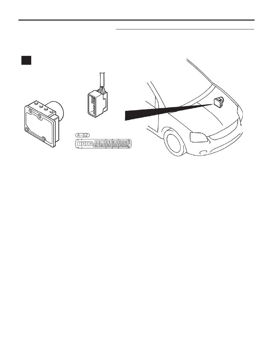
STEP 6. Check ABS-ECU connector A-02 and wheel speed 
sensor <front: RH> connector A-01 for loose, corroded or 
damaged terminals, or terminals pushed back in the 
connector.

Q: Are ABS-ECU connector A-02 and wheel speed sensor 

<front: RH> connector A-01 damaged?
YES : 
Repair or replace the damaged component(s). Refer 

to GROUP 00E, Harness Connector Inspection 

P.00E-2

. Then go to Step 16.

NO :  Go to Step 7.

35DB090A

A

ANTI-LOCK BRAKING SYSTEM (ABS) DIAGNOSIS

ANTI-LOCK BRAKING SYSTEM (ABS)

35B-18

STEP 7. Check the harness wires and continuity resistance  
between ABS-ECU connector A-02 (terminal 9, 10) and 
wheel speed sensor <front: RH> connector A-01 (terminal 
2, 1). (see figure and table below)

NOTE: The special tool (Inspection test harness) MB991219 
for connector pin contact pressure should be used. The test 
probe should never be forcibly inserted, as it may cause a 
defective contact.

35DB090A

A

ABS-ECU
 CONNECTOR
 (A-02)

Supply

Signal

WHEEL SPEED
    SENSOR

Wheel speed 
sensor connectors:
A-04,  A-01,  D-31,  D-30

Terminals:
 5, 10, 17, 19

35DB123A

Terminals:
 16, 9, 6, 8

ANTI-LOCK BRAKING SYSTEM (ABS) DIAGNOSIS

ANTI-LOCK BRAKING SYSTEM (ABS)

35B-19

Q: Is the harness wire between ABS-ECU connector A-02 

(terminal 9, 10) and wheel speed sensor <front: RH> 
connector A-01 (terminal 2, 1) damaged?
YES : 
Repair the wiring harness. Then go to Step 16.
NO :  Go to Step 14.

STEP 8. Check ABS-ECU connector A-02 and wheel speed 
sensor <front: LH> connector A-04 for loose, corroded or 
damaged terminals, or terminals pushed back in the 
connector.

Q: Are ABS-ECU connector A-02 and wheel speed sensor 

<front: LH> connector A-04 damaged?
YES : 
Repair or replace the damaged component(s). Refer 

to GROUP 00E, Harness Connector Inspection 

P.00E-2

. Then go to Step 16.

NO :  Go to Step 9.

              SIGNAL

   TERMINAL  NO.

  NORMAL CONDITION

 ABS (A-02)

   SENSOR

FR wheel speed sensor  
(A-01)

9

2

Less than 2 ohms

10

1

Less than 2 ohms

RR wheel speed sensor  
(D-30)

8

1

Less than 2 ohms

19

2

Less than 2 ohms

FL wheel speed sensor   
(A-04)

16

2

Less than 2 ohms

5

1

Less than 2 ohms

RL wheel speed sensor   
(D-31)

6

1

Less than 2 ohms

17

2

Less than 2 ohms

ANTI-LOCK BRAKING SYSTEM (ABS) DIAGNOSIS

ANTI-LOCK BRAKING SYSTEM (ABS)

35B-20

STEP 9. Check the harness wires and continuity resistance 
between ABS-ECU connector A-02 (terminal 5, 16) and 
wheel speed sensor <front: LH> connector A-04 (terminal 
1, 2). (see figure and table below).

NOTE: The special tool (Inspection test harness) MB991219 
for connector pin contact pressure should be used. The test 
probe should never be forcibly inserted, as it may cause a 
defective contact.

35DB090A

A

ABS-ECU
 CONNECTOR
 (A-02)

Supply

Signal

WHEEL SPEED
    SENSOR

Wheel speed 
sensor connectors:
A-04,  A-01,  D-31,  D-30

Terminals:
 5, 10, 17, 19

35DB123A

Terminals:
 16, 9, 6, 8


Content   ..  946  947  948  949   ..