Mitsubishi 380. Manual - part 940
MULTI-CENTER DISPLAY
CHASSIS ELECTRICAL
54A-294
TROUBLESHOOTING HINTS
• Refer to circuit diagrams GROUP-
• Refer to configuration diagrams GROUP-
• Malfunction of multi-centre display unit
• Malfunction of A/C-ECU
• The wiring harness or connectors may have
loose, corroded, or damaged terminals, or termi-
nals pushed back in the connector.
DIAGNOSIS
Required Special Tools:
• MB991958: Diagnostic Tool (MUT-III Sub Assembly)
• MB991824: Vehicle Communication Interface (V.C.I.)
• MB991827: MUT-III USB Cable
• MB991911: MUT-III Main Harness A (Vehicles with CAN
communication system)
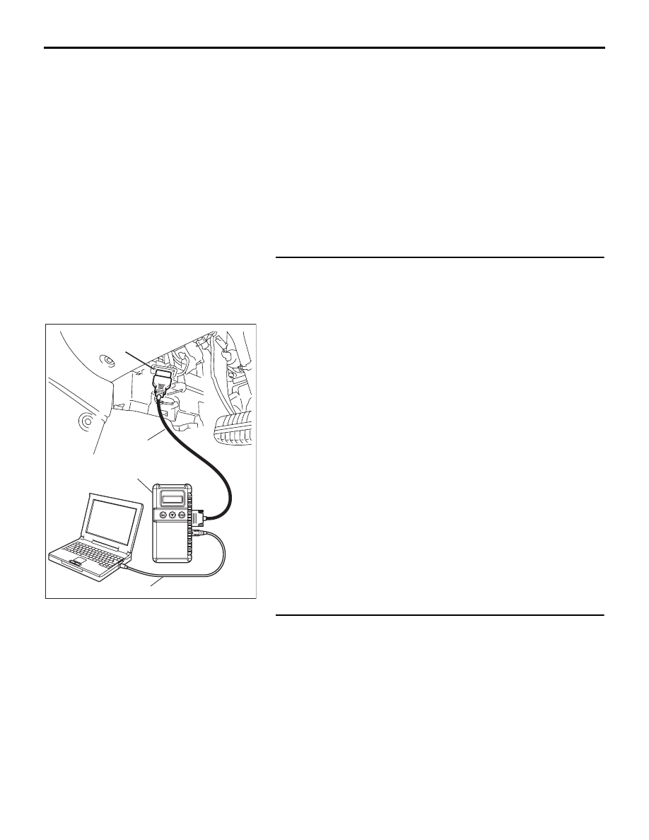
STEP 1. Using diagnostic tool MB991958, diagnose the
CAN bus line
Use diagnostic tool MB991958 to diagnose the CAN bus lines.
(1) Connect diagnostic tool MB991958 to the data link
connector.
(2) Turn the ignition switch to "ON" position.
(3) Diagnose the CAN bus line.
Q: Is the check result satisfactory?
YES : Go to Step 2.
NO : Repair the CAN bus lines (Refer to GROUP 54C,
Diagnosis-Can Bus Diagnostic Chart
). After
diagnosing the CAN bus lines, go to Step 3.
STEP 2. Using diagnostic tool MB991958, read A/C
diagnostic trouble code.
Check if an A/C system DTC is set.
Q: Is the DTC set?
YES : Refer to GROUP 55A, Auto A/C Diagnostic Trouble
NO : Replace multi-centre display unit and then go to Step
00DB076A
MB991910
DATA LINK
CONNECTOR
MB991824
MB991827