Mitsubishi 380. Manual - part 930


  Index      Mitsubishi     Mitsubishi 380 - service repair manual 2005 year


Search            


Content   ..  928  929  930  931   ..


Mitsubishi 380. Manual - part 930


MULTI-CENTER DISPLAY

CHASSIS ELECTRICAL

54A-254

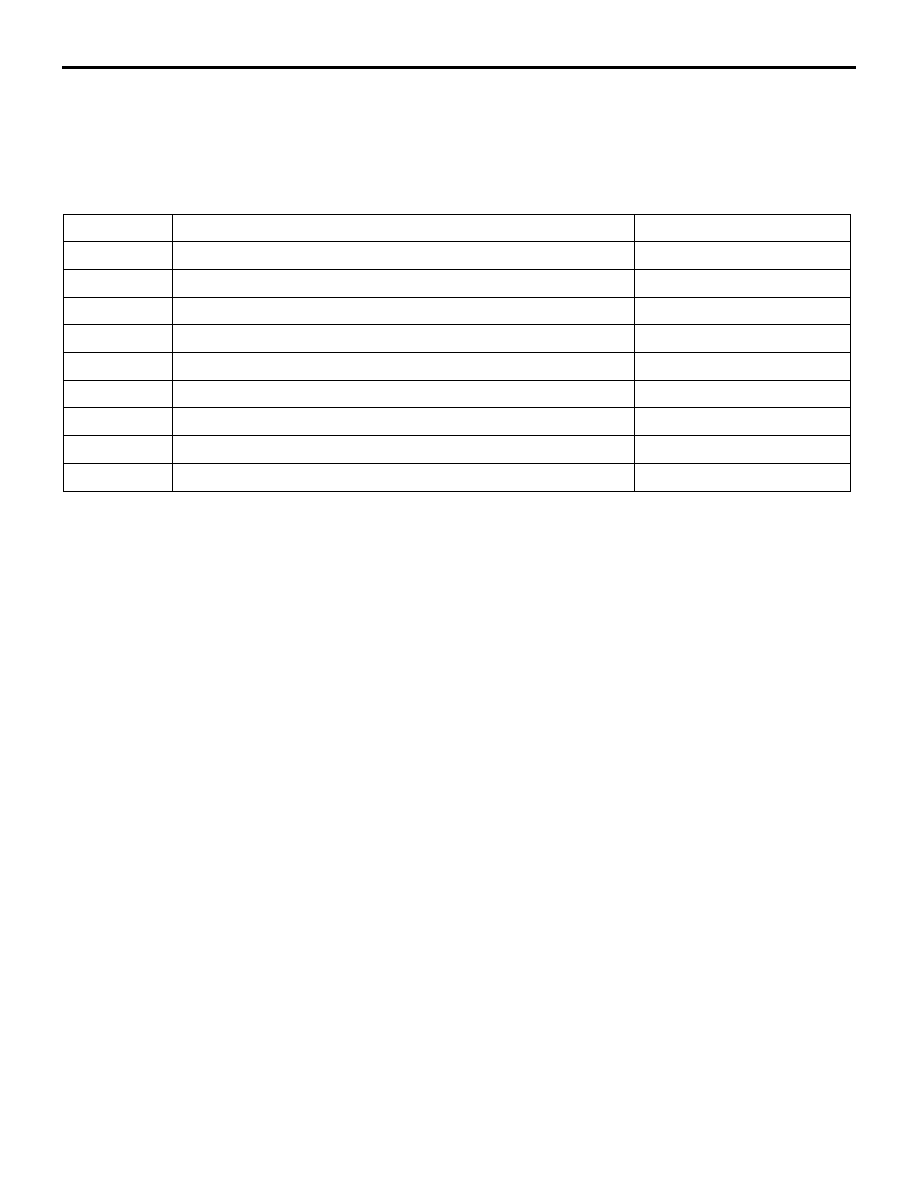
DIAGNOSTIC TROUBLE CODE CHART

M1545001100039

NOTE: During diagnosis, a DTC code associated 
with other system may be set when the ignition 
switch is turned on with connector(s) disconnected. 
On completion, confirm all systems for DTC code(s). 
If DTC code(s) are set, erase them all.

DTC NO.

DIAGNOSTIC ITEM

REFERENCE PAGE

010  (U1073) Bus off

P.54A-255

011  (U1100)

Engine ECU time-out

P.54A-257

012  (U1101) A/T-ECU time-out

P.54A-260

013  (U1110)

A/C-ECU time-out

P.54A-264

014 (U1108)

Combination meter time-out

P.54A-268

019 (U1109)

ETACS-ECU time-out

P.54A-271

020 (U1120)

Failures information on Engine ECU

P.54A-275

021 (U1128)

Failures information on combination meter

P.54A-278

022 (U1130)

Failures information on A/C-ECU

P.54A-281

MULTI-CENTER DISPLAY

CHASSIS ELECTRICAL

54A-255

DIAGNOSTIC TROUBLE CODE PROCEDURES

DTC 010  (U1073): Bus Off

CAUTION

If DTC 010  (U1073) is set in the multi-centre dis-
play, always diagnose the CAN bus lines.

CAUTION

Whenever the ECU is replaced, ensure that the 
communication circuit is normal.

.

CIRCUIT OPERATION

The multi-centre display unit is linked to CAN com-
munication lines to communicate with the combina-
tion meter and the Engine ECU, both of which have a 
terminator resistor.

.

DTC SET CONDITION

If the multi-centre display ceases communicating 
once (i.e. bus off) and then returns to it, the 
multi-centre display will not communicate for three 
minutes immediately after that point. This 
three-minute period is called "Penalty mode." Imme-
diately after the multi-centre display returns to com-
munication, the DTC is set.

.

TECHNICAL DESCRIPTION (COMMENT)

The CAN bus line wiring harness, connector(s), or 
the multi-centre display unit may be defective.

.

16DB402A

A-02 (GR)

CONNECTOR: A-02 

A-02 HARNESS CONNECTOR:

16DB407A

COVER

ENGINE

CONTROL

UNIT

AIR

CLEANER

A/T

CONTROL

UNIT

16DB551A

C-05 (B)

CONNECTOR: C-05

54DB024A

C-02

C-29

C-101

C-125 (B)

CONNECTORS: C-02, C-29, C-101, C-125

MULTI-CENTER DISPLAY

CHASSIS ELECTRICAL

54A-256

TROUBLESHOOTING HINTS

• Refer to circuit diagrams GROUP-

90

• Refer to configuration diagrams GROUP-

80

• The wiring harness or connectors may have 

loose, corroded, or damaged terminals, or termi-
nals pushed back in the connector.

• Malfunction of multi-centre display unit

DIAGNOSIS

Required Special Tools:

• MB991958: Diagnostic Tool (MUT-III Sub Assembly)

• MB991824: Vehicle Communication Interface (V.C.I.)

• MB991827: MUT-III USB Cable

• MB991911: MUT-III Main Harness A (Vehicles with CAN 

communication system)

STEP 1. Using diagnostic tool MB991958, diagnose the 
CAN bus line.
Use diagnostic tool MB991958 to diagnose the CAN bus lines.
(1) Connect diagnostic tool MB991958 to the data link 

connector.

(2) Turn the ignition switch to "ON" position.
(3) Diagnose the CAN bus line.

Q: Is the check result satisfactory?

YES : Go to Step 2.
NO :  Repair the CAN bus lines.  (Refer to GROUP 54C, 

Diagnosis-Can Bus Diagnostic Chart 

P.54C-15

). On 

completion, go to step 3.

STEP 2. Recheck for diagnostic trouble code.
Recheck if the DTC is set.

1. Erase the DTC.
2. Turn the ignition switch to "ON" position.
3. Check if the DTC is set.

Q: Is the check result satisfactory?

YES : Intermittent malfunction is suspected. Refer to 

GROUP 00, How to Use Troubleshooting/Inspection 
Service Points - How to Cope with Intermittent 
Malfunction 

P.00-14

.

NO :  Replace combination meter and then go to step 3.

00DB076A

MB991910

DATA LINK

CONNECTOR

MB991824

MB991827

MULTI-CENTER DISPLAY

CHASSIS ELECTRICAL

54A-257

STEP 3. Recheck for diagnostic trouble code.
Recheck if the DTC is set.

1. Erase the DTC.
2. Turn the ignition switch to "ON" position.
3. Check if the DTC is set.

Q: Is the check result satisfactory?

YES : The procedure is complete.
NO :  Go to Step 1.

DTC 011 (U1100): Engine ECU Time-out

CAUTION

If DTC 011 is set in the multi-centre display, 
always diagnose the CAN bus lines.

CAUTION

Whenever the ECU is replaced, ensure that the 
communication circuit is normal.

.

CIRCUIT OPERATION

 Refer to 

P.54A-255

.

.

DTC SET CONDITION

DTC 011  (U1100)

• The multi-centre display unit receives engine 

control system-related signals from the 
Engine-ECU via CAN bus lines. If the display unit 
can not receives the necessary signals, DTC 011 
(U1100) will be set.

.

TECHNICAL DESCRIPTION (COMMENT)

CAUTION

If the ignition switch is turned to the ON position 
without starting the engine, DTC (past trouble) 
013  (U1110) and 014 (U1108) may be set on the 
combination meter (incorporating meter-ECU) 
after three minutes.

Current trouble

• Connector(s) or wiring harness in the CAN bus 

lines between the Engine ECU and the 
multi-centre display unit, the power supply sys-
tem to the display unit, the display unit itself, or 
the Engine ECU may be defective.

Past trouble

• Carry out diagnosis with  particular emphasis on 

connector(s) or wiring harness in the CAN bus 
lines between the Engine ECU and the 
multi-centre display unit, and the power supply 
system to the Engine ECU. For diagnosis proce-
dures, refer to "How to cope with past trouble" 
(Refer to GROUP 00, How to Use Troubleshoot-
ing/Inspection Service Points 

P.00-14

).

NOTE: For a past trouble, you may not find it by 
the MUT-III CAN bus diagnostics even if there is 
any failure in CAN bus lines. In this case, refer to 
GROUP 00, How to Use Troubleshooting/Inspec-
tion Service Points - How to Cope with Intermit-
tent Malfunction 

P.00-14

.) and check the CAN 

bus lines. You can narrow down the possible 
cause of the trouble by referring to the DTC, 
which is set regarding the CAN communica-
tion-linked ECUs (Refer to GROUP 54C, CAN 
bus line Diagnostics Flow 

P.54C-6

).

.

TROUBLESHOOTING HINTS

• Refer to circuit diagrams GROUP-

90

• Refer to configuration diagrams GROUP-

80

• The wiring harness or connectors may have 

loose, corroded, or damaged terminals, or termi-
nals pushed back in the connector.

• Malfunction of Engine ECU.

• Malfunction of multi-centre display unit


Content   ..  928  929  930  931   ..