Mitsubishi 380. Manual - part 929


  Index      Mitsubishi     Mitsubishi 380 - service repair manual 2005 year


Search            


Content   ..  927  928  929  930   ..


Mitsubishi 380. Manual - part 929


MULTI-CENTER DISPLAY

CHASSIS ELECTRICAL

54A-250

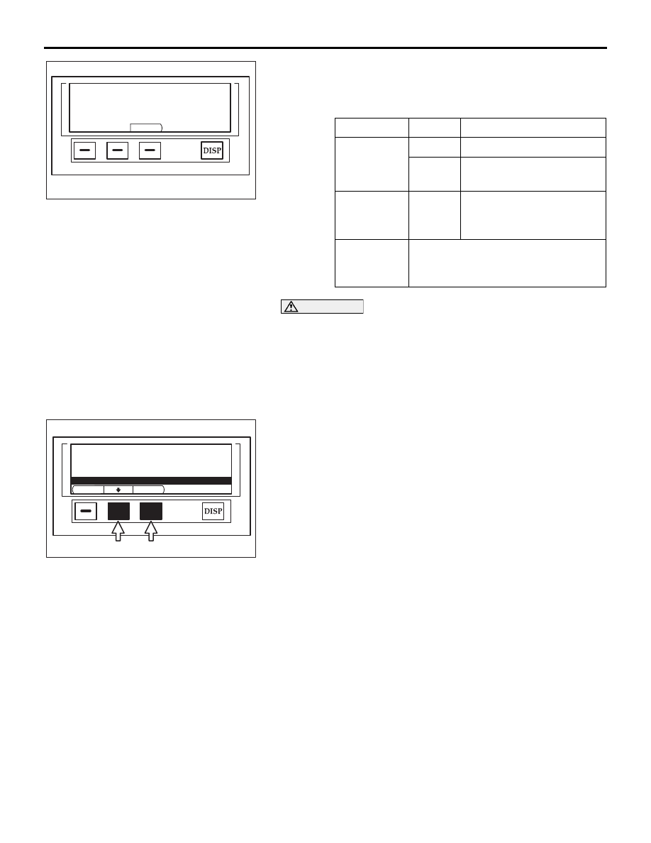
2. The multi-centre display performs check and displays the 

check result. Operate the lighting switch or the ignition 
switch. Check whether the multi-centre display screen 
corresponds to that operation. 

CAUTION

The "Compass check" mode  will be displayed on the 
multi-centre display but will not be accessible due to not 
being available on vehicle.

.

Auto check

1. Activate the service mode start-up screen.
2. Turn the ignition switch to  "ON" position.

.  3. Choose "Auto check" by pressing function button switch 2.

4. Execute "ENTER" by pressing the function button switch 3.
5. The multi-centre display unit checks the communication 

condition, and then shows the check results of 
"Communication check", "Monitor check"  and "Vehicle 
check". Then the multi-centre display ceases CAN 
communication in approximately seven seconds.

.

Release of service mode

Move from the check result screen to the service mode start-up 
screen by pressing "ENTER" above function button switch 3. If 
you press "BACK" above function button switch 1 during pro-
cessing, the checks will be cancelled and the screen returns to 
service mode start-up screen.

Fail-safe function of the multi-centre display unit

If abnormal power supply voltage or abnormally high tempera-
ture is detected in the multi-centre display unit, a fail-safe func-
tion will be activated to protect the unit, and then blank the 
screen.

Fail-safe function is activated when:
Power supply voltage is abnormal

• Excessively low voltage: Power supply voltage remains 

9 volts or less for approximately 10 seconds.

• Excessively high voltage: Power supply voltage remains 

17 volts or more for approximately 10 seconds.

Abnormally high temperature is detected in the unit.

• Internal temperature remains 95°C for 60 seconds.

CHECK ITEM DISPLAY CONTENT OR CONDITION

Illumination

ILL: ON

 If the lighting switch is ON

ILL: 
OFF

If the lighting switch is OFF

ignition 
switch 
position

• IG

• ACC

Displays the current 
position of the ignition 
switch.

Battery 
positive 
voltage

Displays the voltage.

Vehicle signal check

ILL                       : OFF

Key position       : ACC

Voltage                : 14.9V

ENTER

AC208706AB

BACK

ENTER

Service  mode

1. Communication  check

2. Monitor  check

3. Compass  check

4. Vehicle  check

5. Auto  check

AC208707AB

MULTI-CENTER DISPLAY

CHASSIS ELECTRICAL

54A-251

If an abnormal voltage or temperature is detected, the 
multi-centre display unit will sound its buzzer to indicate this 
and activate a message to blank the screen in approximately 
seven seconds.

NOTE: The unit blanks the screen immediately when the power 
supply voltage reaches 18 volts.

Fail-safe function is deactivated when:
Power supply voltage is abnormal

• The fail-safe function will be deactivated if the power 

supply voltage remains 10 volts or more for approxi-
mately five seconds, or the ignition switch is turned to 
the "LOCK" (OFF) position.

• The fail-safe function will be deactivated if the power 

supply voltage remains 17 volts or less for approxi-
mately five seconds or more, or the ignition switch is 
turned to the "LOCK" (OFF) position.

Abnormally high temperature is detected in the unit.

• The fail-safe function will be deactivated if its internal 

temperature has reduced to 85

°C  or less, or the ignition 

switch is turned to the "LOCK" (OFF) position.

DIAGNOSIS FUNCTION

M1543007000465

ON-BOARD DIAGNOSTICS

The multi-centre display monitors its input/output sig-
nals (some signals all the time and others under 
specified conditions). When an irregular signal is ini-
tially monitored, the multi-centre display decides that 
a malfunction has occurred and records the occur-
rence as a diagnostic trouble code. There are 9 diag-
nostic items. The diagnostic results can be read with 
a diagnostic tool MB991958 (MUT-III sub assembly). 
Diagnostic trouble codes are kept in memory by 
direct battery feed. The codes are retained in mem-
ory even if the ignition switch is in the "LOCK" (OFF) 

position. Diagnostic trouble codes will, however, be 
erased when a battery terminal or the multi-centre 
display connector is disconnected. In addition, the 
diagnostic trouble code can also be erased by 
diagnostic tool MB991958 (MUT-III sub assembly).

NOTE: If a connector or sensor is disconnected 
when the ignition switch is in the "ON" position, a 
diagnostic trouble code is stored in memory. In this 
case, erase the DTC using the diagnostic tool.

NOTE: The 9 diagnostic items are displayed in 
numeric order.

HOW TO CONNECT DIAGNOSTIC TOOL (MUT-III)

Required Special Tools:

• MB991958: Diagnostic Tool (MUT-III Sub Assembly)

• MB991824: Vehicle Communication Interface (V.C.I.)

• MB991827: MUT-III USB Cable

• MB991911: MUT-III Main Harness A (Vehicles with CAN 

communication system)

CAUTION

To prevent damage to diagnostic tool MB991958, always 
turn the ignition switch to the "LOCK" (OFF) position 
before connecting or disconnecting diagnostic tool 
MB991958.

MULTI-CENTER DISPLAY

CHASSIS ELECTRICAL

54A-252

1. Ensure that the ignition switch is at the "LOCK" (OFF) 

position.

2. Start up the personal computer.

3. Connect special tool MB991827 to special tool MB991824 

and the personal computer.

4. Connect special tool MB991910 to special tool MB991824.

5. Connect special tool MB991910 to the data link connector.

6. Turn the power switch of special tool MB991824 to the "ON" 

position.

NOTE: When special tool MB991824 is energized, special 
tool MB991824 indicator light will be illuminated in a green 
color.

7. Start the MUT-III system on the personal computer.

NOTE: Disconnecting the diagnostic tool MB991958 is the 
reverse of the connecting sequence, making sure that the 
ignition switch is at the "LOCK" (OFF) position.

00DB076A

MB991910

DATA LINK

CONNECTOR

MB991824

MB991827

MULTI-CENTER DISPLAY

CHASSIS ELECTRICAL

54A-253

HOW TO READ AND ERASE DIAGNOSTIC 
TROUBLE CODES

Required Special Tools:

• MB991958: Diagnostic Tool (MUT-III Sub Assembly)

• MB991824: Vehicle Communication Interface (V.C.I.)

• MB991827: MUT-III USB Cable

• MB991911: MUT-III Main Harness A (Vehicles with CAN 

communication system)

CAUTION

To prevent damage to diagnostic tool MB991958, always 
turn the ignition switch to the "LOCK" (OFF) position 
before connecting or disconnecting diagnostic tool 
MB991958.

NOTE: If the battery voltage is low, diagnostic trouble codes will 
not be set. Check the battery if diagnostic tool MB991958 does 
not display.
1. Connect diagnostic tool MB991958 to the data link 

connector.

2. Turn the ignition switch to "ON" position.

3. Select "Interactive Diagnosis" from the start-up screen.

4. Select "System select."

5. Choose "Display" .

6. Select "Diagnostic Trouble Code."

7. If a DTC is set, it is shown.

8. Choose "Erase DTCs" to erase the DTC.

00DB076A

MB991910

DATA LINK

CONNECTOR

MB991824

MB991827


Content   ..  927  928  929  930   ..