Mitsubishi 380. Manual - part 899


  Index      Mitsubishi     Mitsubishi 380 - service repair manual 2005 year


Search            


Content   ..  897  898  899  900   ..


Mitsubishi 380. Manual - part 899


COMBINATION METER ASSEMBLY

CHASSIS ELECTRICAL

54A-130

STEP 4. Check the speedometer and buzzer function.
Check the input signals from the following switch:

• Ignition switch: ON

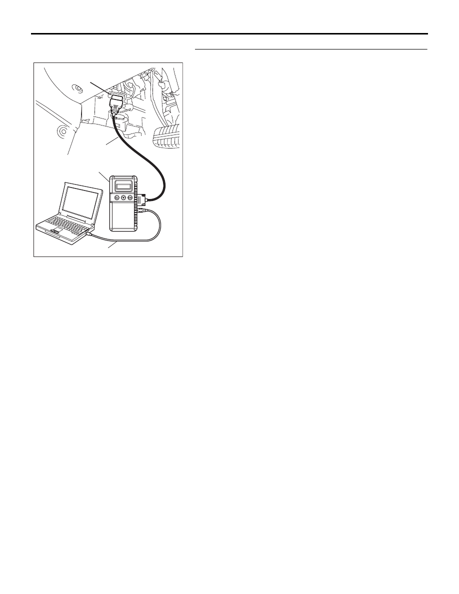
Use diagnostic tool MB991958 to enter simulated vehicle 
speed.
(1) Connect diagnostic tool MB991958 to the data link 

connector.

(2) Turn the ignition switch to "ON" position.
(3) Select "Interactive Diagnosis" from the start-up screen.
(4) Select "System Select."
(5) Choose "Meter" .
(6) Select "Simulated vehicle Speed Output."
(7) Confirm if speed alarm "BEEPS"

Q: Does speed alarm "BEEP" when set speed is exceeded?

YES : The procedure is complete.
NO :  Replace the ETACS-ECU.

00DB076A

MB991910

DATA LINK

CONNECTOR

MB991824

MB991827

COMBINATION METER ASSEMBLY

CHASSIS ELECTRICAL

54A-131

INSPECTION PROCEDURE 16: Speed alarm set speed cannot be adjusted and/ or turned off and/ or 
operating mode cannot be changed.

NOTE: This troubleshooting procedure requires the 
use of diagnostic tool MB991958 and SWS monitor 
kit MB991813. For details on how to use the SWS 
monitor, refer to "How to connect SWS monitor 

P.54B-13

."

.

CIRCUIT OPERATION

The ETACS-ECU controls the speed alarm warning 
tone alarm, based on the signals from the switches 
and sensors below.

• Ignition switch (IG1): ON

• mode switch signals "MODE", "UP" and "DOWN".

.

TECHNICAL DESCRIPTION (COMMENT)

If the speed alarm mode switch does not  work, con-
nector(s), wiring harness in the mode switch and the 
combination meter  circuits may be defective.

.

TROUBLESHOOTING HINTS

• Refer to circuit diagrams GROUP-

90

• Refer to configuration diagrams GROUP-

80

• Mode switch input signals to the combination 

meter.

• The wiring harness or connectors may have 

loose, corroded, or damaged terminals, or termi-
nals pushed back in the connector

• The trip computer/ combination meter may be 

defective

• The Engine-ECU, A/T-ECU or ETACS-ECU may 

be defective

ETACS-

ECU

MODE SWITCH

SIGNAL

· IGNITION SWITCH (IG1)

COMBINATION 

METER

CPU

CAN COMMUNICATION LINE

(CAN_L LINE)

CAN COMMUNICATION LINE

(CAN_H LINE)

 Mode Switch Function Circuit

16DB585A

MODE
SWITCH

16DB586A

54DB019A

CONNECTOR: C-101

HARNESS SIDE

COMBINATION METER ASSEMBLY

CHASSIS ELECTRICAL

54A-132

REMOVAL SERVICE POINT

.

<<A>> MODE SELECT SWITCH REMOVAL

Remove the mode select switch by removing the screws that 
attach the switch to the cover.

MODE SELECT SWITCH CONTINUITY CHECK

NOTE: If any of the below specifications are not met, replace 
the mode switch.

DIAGNOSIS

Required Special Tool:

• MB991223: Harness set

STEP 1. Check combination meter connector C-101 for 
loose, corroded or damaged terminals, or terminals 
pushed back in the connector.
Q: Is combination meter connector C-101 in good 

condition?
YES : 
Go to Step 2.
NO :  Repair or replace the component(s). Refer to GROUP 

00E, Harness Connector Inspection 

P.00E-2

. The 

mode switch and combination meter works normally.

SWITCH POSITION TESTER 

CONNECTION

SPECIFIED 
CONDITION

Mode select "ON" 
(depress)

− 6

Less than 2 ohms

Mode select "OFF" 
(released)

− 6

Open circuit

Mode select "UP" 
(depress)

− 6

Less than 2 ohms

Mode select "UP" 
(released)

− 6

Open circuit

Mode select 
"DOWN" (depress)

− 6

Less than 2 ohms

Mode select 
"DOWN" (released)

− 6

Open circuit

16DB589A

MODE SELECT SWITCH

54DB019A

CONNECTOR: C-101

HARNESS SIDE

COMBINATION METER ASSEMBLY

CHASSIS ELECTRICAL

54A-133

STEP 2. Measure at combination meter connector C-101 in 
order to power supply circuit to combination meter 
(battery power supply).
(1) Disconnect combination meter connector C-101, and 

measure at the wiring harness side.

(2) Turn the ignition switch to "LOCK" (OFF) position.

(3) Measure the voltage between terminal 1 and ground. 

• The voltage should measure approximately 12 volts 

(battery positive voltage).

Q: Is the measured voltage approximately 12 volts (battery 

positive voltage)?
YES : 
Go to Step 4.
NO :  Go to Step 3.

STEP 3. Check the wiring harness between combination 
meter connector C-101 (terminal 1) and the fuse No.22.

NOTE: Also check intermediate connector C-29 for loose, cor-
roded, or damaged terminals, or terminals pushed back in the 
connector. If intermediate connector C-29 is damaged, repair or 
replace. Refer to GROUP 00E, Harness Connector Inspection 

P.00E-2

Q: Is the wiring harness between combination meter 

connector C-101 (terminal 1) and the fuse No.22 in good 
condition?
YES : 
Retest the system.
NO :  Repair the wiring harness. Check that the mode 

switch and combination meter works normally.

54DB019A

CONNECTOR: C-101

HARNESS SIDE

AC209365

CONNECTOR C-101 
(HARNESS SIDE)

HT


Content   ..  897  898  899  900   ..