Mitsubishi 380. Manual - part 897


  Index      Mitsubishi     Mitsubishi 380 - service repair manual 2005 year


Search            


Content   ..  895  896  897  898   ..


Mitsubishi 380. Manual - part 897


COMBINATION METER ASSEMBLY

CHASSIS ELECTRICAL

54A-122

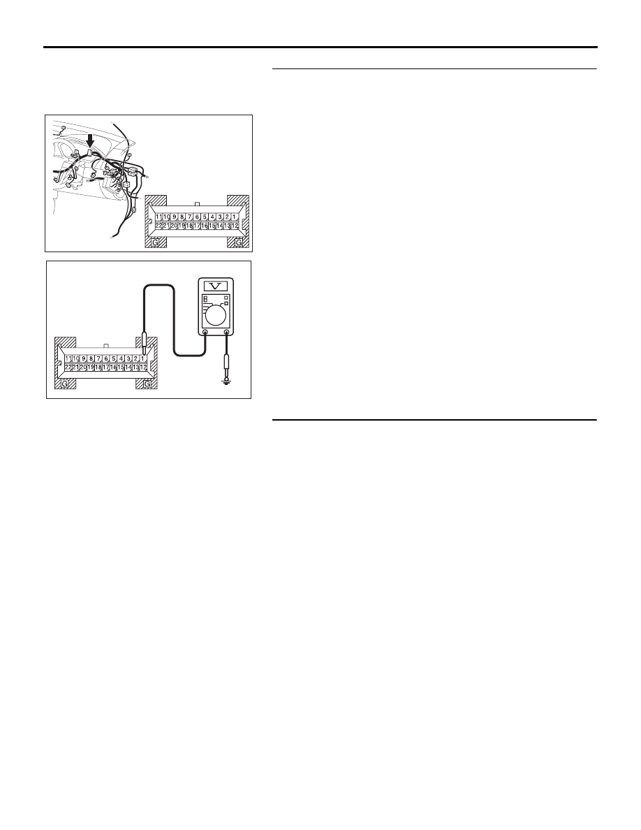
STEP 2. Measure at combination meter connector C-101 in 
order to power supply circuit to combination meter 
(battery power supply).
(1) Disconnect combination meter connector C-101, and 

measure at the wiring harness side.

(2) Turn the ignition switch to "LOCK" (OFF) position.

(3) Measure the voltage between terminal 1 and ground. 

• The voltage should measure approximately 12 volts 

(battery positive voltage).

Q: Is the measured voltage approximately 12 volts (battery 

positive voltage)?
YES : 
Go to Step 4.
NO :  Go to Step 3.

STEP 3. Check the wiring harness between combination 
meter connector C-101 (terminal 1) and the fuse No.22.

NOTE: Also check intermediate connector C-29 for loose, cor-
roded, or damaged terminals, or terminals pushed back in the 
connector. If intermediate connector C-29 is damaged, repair or 
replace. Refer to GROUP 00E, Harness Connector Inspection 

P.00E-2

Q: Is the wiring harness between combination meter 

connector C-101 (terminal 1) and the fuse No.22 in good 
condition?
YES : 
Retest the system.
NO :  Repair the wiring harness. Check that the  

combination meter works normally.

54DB019A

CONNECTOR: C-101

HARNESS SIDE

AC209365

CONNECTOR C-101 
(HARNESS SIDE)

HT

COMBINATION METER ASSEMBLY

CHASSIS ELECTRICAL

54A-123

STEP 4. Measure the voltage at combination meter 
connector C-101 in order to power supply circuit to 
combination meter (IG1 power supply).
(1) Disconnect combination meter connector C-101, and 

measure at the wiring harness side.

(2) Turn the ignition switch to "ON" position.

(3) Measure the voltage between terminal 12 and ground. 

• The voltage should measure approximately 12 volts 

(battery positive voltage).

Q: Is the measured voltage approximately 12 volts (battery 

positive voltage)?
YES : 
Go to Step 6.
NO :  Go to Step 5.

STEP 5. Check the wiring harness between combination 
meter connector C-101 (terminal 12) and the ignition 
switch (IG1)

NOTE: Also check  junction block connector C-211 and C-215 
for loose, corroded, or damaged terminals, or terminals pushed 
back in the connector. If inspecting junction block connector 
C-211 or C-215 is damaged, repair or replace. Refer to 
GROUP 00E, Harness Connector Inspection 

P.00E-2

Q: Is the wiring harness between combination meter 

connector C-101 (terminal 12) and the ignition switch 
(IG1) in good condition?
YES : 
Retest the system.
NO :  Repair the wiring harness. Check that the  

combination meter works normally.

54DB019A

CONNECTOR: C-101

HARNESS SIDE

AC209365

CONNECTOR C-101 
(HARNESS SIDE)

HU

25DB096A

CONNECTORS: C-211, C-215

HARNESS SIDE

C-211

HARNESS SIDE

C-215

COMBINATION METER ASSEMBLY

CHASSIS ELECTRICAL

54A-124

STEP 6. Measure the resistance at combination meter 
connector C-101 in order to the ground circuit to the 
combination meter.
(1) Disconnect combination meter connector C-101, and 

measure at the wiring harness side.

(2) Measure the resistance value between terminal 3, 5 and 

ground.

• The resistance should be 2 ohms or less.

Q: Is the measured resistance 2 ohms or less?

YES : Go to Step 8.
NO :  Go to Step 7.

STEP 7. Check the wiring harness between combination 
meter connector C-101 (terminal 3 and 5) and ground.
Q: Is the wiring harness between combination meter 

connector C-101 (terminal 3 and 5) and ground in good 
condition?
YES : 
Procedure is complete. Retest the system.
NO :  Repair the wiring harness. Check that the mode witch 

and combination meter works normally.

STEP 8. Retest the system.

Q: Is the check result satisfactory?

YES : Go to Step 9
NO :  Replace the combination meter.

54DB019A

CONNECTOR: C-101

HARNESS SIDE

AC209364

CONNECTOR C-101 
(HARNESS SIDE)

JR

54DB019A

CONNECTOR: C-101

HARNESS SIDE

COMBINATION METER ASSEMBLY

CHASSIS ELECTRICAL

54A-125

STEP 9. Using diagnostic tool MB991958, diagnose the 
CAN bus line.
(1) Connect diagnostic tool MB991958 to the data link 

connector.

(2) Turn the ignition switch to "ON" position.
(3) Diagnose the CAN bus line.

Q: Is the check result satisfactory?

YES : Go to Step 10.
NO :  Repair the CAN bus lines (Refer to GROUP 54C, 

Diagnosis-Can Bus Diagnostic Chart 

P.54C-15

). On 

completion, go to Step 12.

STEP 10. Using diagnostic tool MB991958, read A/T 
diagnostic trouble code.
Check if an A/T system or Engine (MPI) system DTC is set.

Q: Is the DTC set?

YES : Refer to GROUP 23A, Automatic Transmission 

Diagnosis or GROUP 13A Engine (MPI) 

− Diagnostic 

Trouble Code Chart 

P.23A-34

, or refer to Output 

speed sensor system

P.23A-72

. On completion, go to 

Step 12.

NO :  Go to Step 11.

STEP 11. Check the speedometer
Use diagnostic tool MB991958 to enter simulated vehicle 
speed.
(1) Connect diagnostic tool MB991958 to the data link 

connector.

(2) Turn the ignition switch to "ON" position.
(3) Select "Interactive Diagnosis" from the start-up screen.
(4) Select "System Select."
(5) Choose "Meter" .
(6) Select "Simulated vehicle Speed Output."

OK: The speedometer shows that simulated vehi-
cle speed.

Q: Is the check result satisfactory?

YES : Go to Step 12.
NO :  Replace the combination meter, then go to Step 12.

00DB076A

MB991910

DATA LINK

CONNECTOR

MB991824

MB991827


Content   ..  895  896  897  898   ..