Mitsubishi 380. Manual - part 884
COMBINATION METER ASSEMBLY
CHASSIS ELECTRICAL
54A-70
SYMPTOM PROCEDURES
INSPECTION PROCEDURE 1:Communication With Diagnostic Tool is Not Possible.
.
CIRCUIT OPERATION
The combination meter is linked to the data link con-
nector via CAN bus line to communicate with the
diagnostic tool.
.
TECHNICAL DESCRIPTION (COMMENT)
If the system does not communicate with diagnostic
tool, power supply to data link connector or CAN bus
lines may be defective.
.
TROUBLESHOOTING HINTS
• Refer to circuit diagrams GROUP-
• Refer to configuration diagrams GROUP-
• The wiring harness or connectors may have
loose, corroded, or damaged terminals, or termi-
nals pushed back in the connector.
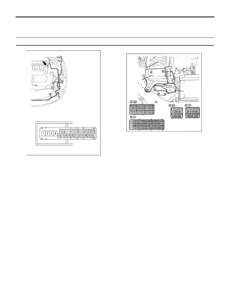
16DB402A
A-02 (GR)
CONNECTOR: A-02
A-02 HARNESS CONNECTOR:
16DB407A
COVER
ENGINE
CONTROL
UNIT
AIR
CLEANER
A/T
CONTROL
UNIT