Mitsubishi 380. Manual - part 878


  Index      Mitsubishi     Mitsubishi 380 - service repair manual 2005 year


Search            


Content   ..  876  877  878  879   ..


Mitsubishi 380. Manual - part 878


COMBINATION METER ASSEMBLY

CHASSIS ELECTRICAL

54A-46

DIAGNOSIS FUNCTION

M1543007000454

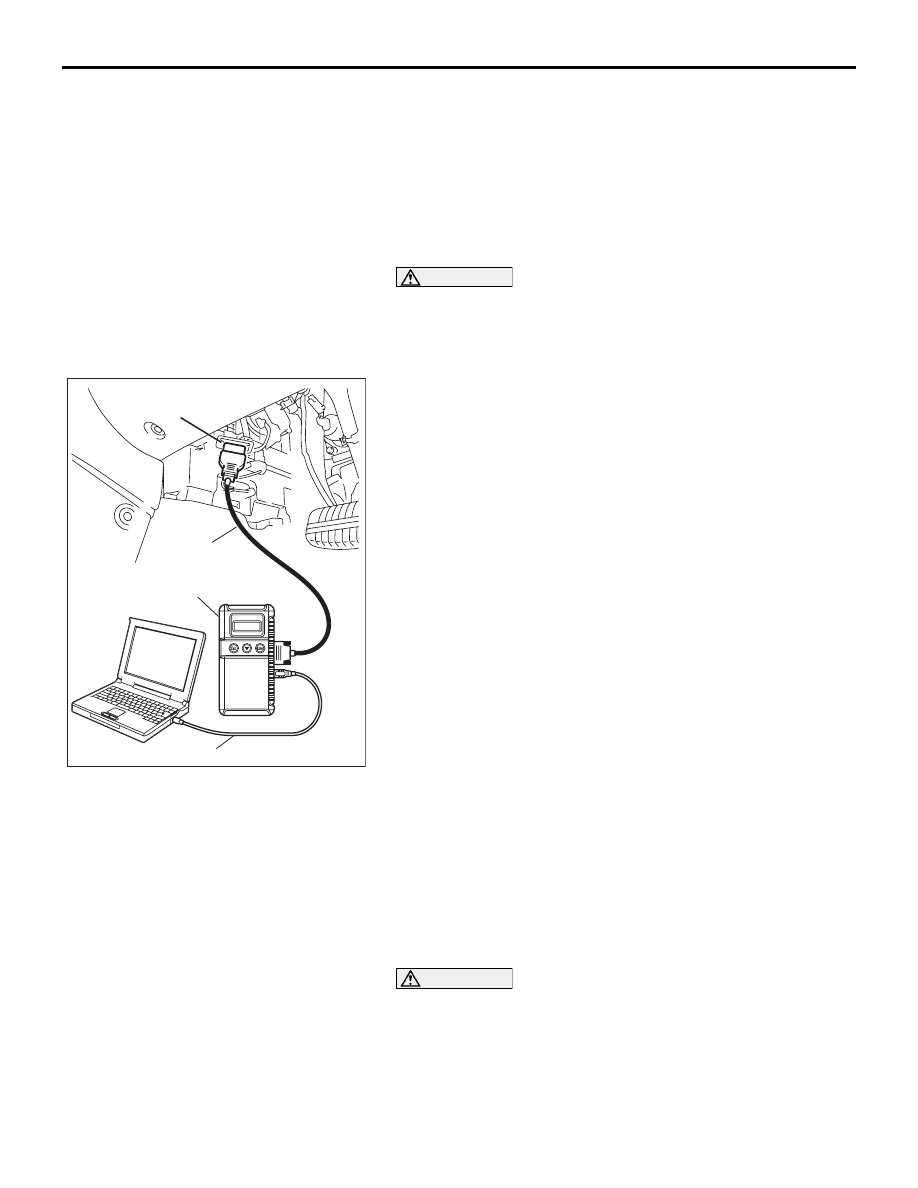
HOW TO CONNECT DIAGNOSTIC TOOL (MUT-III)

Required Special Tools:

• MB991958: Diagnostic Tool (MUT-III Sub Assembly)

• MB991824: Vehicle Communication Interface (V.C.I.)

• MB991827: MUT-III USB Cable

• MB991910: MUT-III Main Harness A (Vehicles with CAN 

communication system)

CAUTION

To prevent damage to diagnostic tool MB991958, always 
turn the ignition switch to the "LOCK" (OFF) position 
before connecting or disconnecting diagnostic tool 
MB991958.
1. Ensure that the ignition switch is at the "LOCK" (OFF) 

position.

2. Start up the personal computer.

3. Connect special tool MB991827 to special tool MB991824 

and the personal computer.

4. Connect special tool MB991910 to special tool MB991824.

5. Connect special tool MB991910 to the data link connector.

6. Turn the power switch of special tool MB991824 to the "ON" 

position.

NOTE: When special tool MB991824 is energized, special 
tool MB991824 indicator light will be illuminated in a green 
color.

7. Start the MUT-III system on the personal computer.

NOTE: Disconnecting the diagnostic tool MB991958 is the 
reverse of the connecting sequence, making sure that the 
ignition switch is at the "LOCK" (OFF) position.

HOW TO READ AND ERASE DIAGNOSTIC 
TROUBLE CODES

Required Special Tools:

• MB991958: Diagnostic Tool (MUT-III Sub Assembly)

• MB991824: Vehicle Communication Interface (V.C.I.)

• MB991827: MUT-III USB Cable

• MB991910: MUT-III Main Harness A (Vehicles with CAN 

communication system)

CAUTION

To prevent damage to diagnostic tool MB991958, always 
turn the ignition switch to the "LOCK" (OFF) position 
before connecting or disconnecting diagnostic tool 
MB991958.

NOTE: If the battery voltage is low, diagnostic trouble codes will 
not be set. Check the battery if diagnostic tool MB991958 does 
not display.

00DB076A

MB991910

DATA LINK

CONNECTOR

MB991824

MB991827

COMBINATION METER ASSEMBLY

CHASSIS ELECTRICAL

54A-47

1. Connect diagnostic tool MB991958 to the data link 

connector.

2. Turn the ignition switch to "ON" position.

3. Select "Interactive Diagnosis" from the start-up screen.

4. Select "System select."

5. Choose "Meter" .

6. Select "Diagnostic Trouble Code."

7. If a DTC is set, it is shown.

8. Choose "Erase DTCs" to erase the DTC.

HOW TO DIAGNOSE THE CAN BUS LINES

Required Special Tools:

• MB991958: Diagnostic Tool (MUT-III Sub Assembly)

• MB991824: Vehicle Communication Interface (V.C.I.)

• MB991827: MUT-III USB Cable

• MB991910: MUT-III Main Harness A (Vehicles with CAN 

communication system)

CAUTION

To prevent damage to diagnostic tool MB991958, always 
turn the ignition switch to the "LOCK" (OFF) position 
before connecting or disconnecting diagnostic tool 
MB991958.

00DB076A

MB991910

DATA LINK

CONNECTOR

MB991824

MB991827

COMBINATION METER ASSEMBLY

CHASSIS ELECTRICAL

54A-48

1. Connect diagnostic tool MB991958 to the data link 

connector.

2. Turn the ignition switch to "ON" position.

3. Select "CAN bus diagnosis" from the start-up screen.

4. When the vehicle information is displayed, confirm that it 

matches the vehicle whose CAN bus lines will be 
diagnosed.

• If they matches, go to step 8.

• If not, go to step 5.

5. Select "view vehicle information" button.

6. Enter the vehicle information and select the "OK" button.

7. When the vehicle information is displayed, confirm again 

that it matches the vehicle whose CAN bus lines will be 
diagnosed.

• If they matches, go to step 8.

• If not, go to step 5.

8. Select the "OK" button.

9. When the optional equipment is displayed, choose the one 

which the vehicle is fitted with, and then select the "OK" 
button.

DIAGNOSTIC TROUBLE CODE CHART

M1543007100440

CAUTION

During diagnosis, a DTC code associated with 
other system may be set when the ignition switch 
is turned on with connector(s) disconnected. On 
completion, confirm all systems for DTC code(s). 
If DTC code(s) are set, erase them all.

00DB076A

MB991910

DATA LINK

CONNECTOR

MB991824

MB991827

DTC NO.

Diagnostic item

REFERENCE PAGE

U1073

Bus off

P.54A-49

U1100

Engine ECU time-out (related to engine)

P.54A-51

U1101

Auto Transmission ECU time-out (related to A/T)

U1102

ABS-ECU time-out

P.54A-55

U1109

ETACS-ECU time-out

P.54A-59

U1112

SRS-ECU time-out

P.54A-62

U1120

Failure information on Engine ECU (related to engine)

P.54A-64

U1206

Flag invalid

P.54A-67

COMBINATION METER ASSEMBLY

CHASSIS ELECTRICAL

54A-49

DIAGNOSTIC TROUBLE CODE PROCEDURES

DTC U1073: Bus Off

CAUTION

If DTC U1073 is set in the combination meter, 
always diagnose the CAN bus lines.

CAUTION

Whenever the ECU is replaced, ensure that the 
communication circuit is normal.

.

CIRCUIT OPERATION

Some instruments of the combination meter are 
linked to the CAN bus line. Both the combination 
meter and the Engine ECU have a terminator resis-
tor.

.

DTC SET CONDITION

If the combination meter ceases communicating 
once (i.e. bus off) and then returns to it, the combina-
tion meter will not communicate for five minutes 
immediately after that point. This five minute period 
is called "Penalty mode." Immediately after the com-
bination meter returns to communication, the DTC is 
set.

.

TECHNICAL DESCRIPTION (COMMENT)

The wiring harness or connectors may have loose, 
corroded, or damage terminals, or terminals pushed 
back in the connector, or the combination meter may 
be defective.

.

TROUBLESHOOTING HINTS

• Refer to circuit diagrams GROUP-

90

• Refer to configuration diagrams GROUP-

80

• The wiring harness or connectors may have 

loose, corroded, or damaged terminals, or termi-
nals pushed back in the connector.

• Malfunction of combination meter.  

A-02 (GR)

CONNECTOR: A-02 

16DB407A

COVER

ENGINE

CONTROL

UNIT

AIR

CLEANER

A/T

CONTROL

UNIT


Content   ..  876  877  878  879   ..