Mitsubishi 380. Manual - part 877
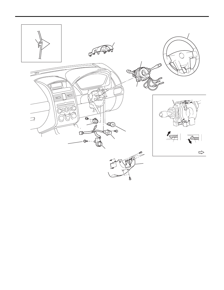
IGNITION SWITCH
CHASSIS ELECTRICAL
54A-42
54DB022A
SECTION A – A
CLAW
2
1
2
3
4
7
2
5
6
A
A
2.5 ± 0.5 N·m
23 ± 4 in-lb
2.0 ± 1.0 N·m
18 ± 9 in-lb
A
B
B
COLUMN SWITCH
CLAW
CLAW
NOTE
A
CLAW POSITIONS:
SECTION A – A
SECTION B – B