Mitsubishi 380. Manual - part 832


  Index      Mitsubishi     Mitsubishi 380 - service repair manual 2005 year


Search            


Content   ..  830  831  832  833   ..


Mitsubishi 380. Manual - part 832


SEAT BELTS WITH PRE-TENSIONER

SUPPLEMENTAL RESTRAINT SYSTEM (SRS)

52B-252

<<B>>PRE-TENSIONER CONNECTOR 
DISCONNECTION

1. Use a flat-tipped screwdriver to unlock the locking button of 

the harness-side connector by withdrawing it toward you in 
two stages.

2. Disconnect the pretensioner connector.

INSTALLATION SERVICE POINTS

.

>>A<< PRE-INSTALLATION INSPECTION

WARNING

Dispose of seat belt pre-tensioner only according to 
the specified procedure. (Refer to 

P.52B-254

).

1. When installing the new seat belt pre-tensioner, refer to 

“INSPECTION” (

P.52B-253

).

2. Connect the negative (

−) battery cable.

CAUTION

To prevent damage to diagnostic tool MB991958, always 
turn the ignition switch to the "LOCK" (OFF) position 
before connecting or disconnecting diagnostic tool 
MB991958.
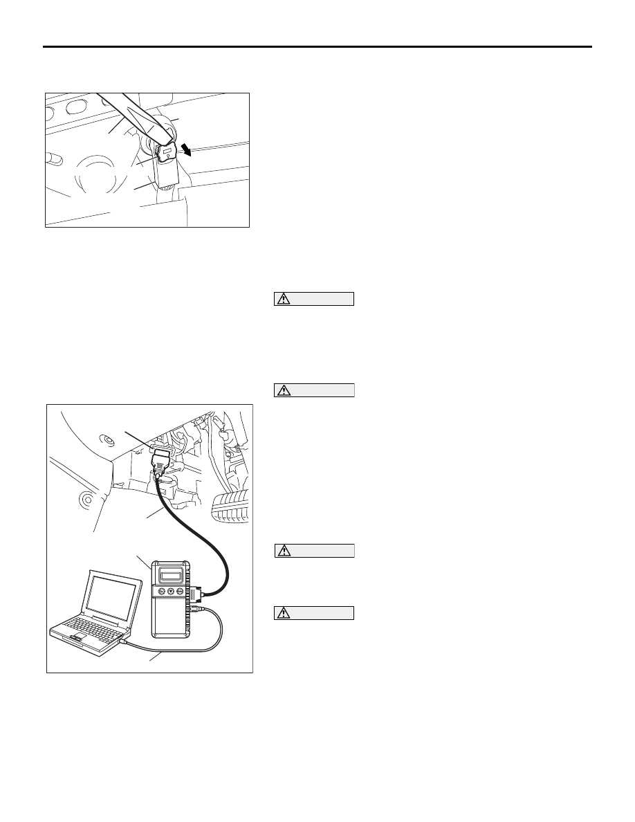
3. Connect diagnostic tool MB991958 to the data link 

connector.

4. Turn the ignition switch to the “ON” position.

5. Check DTCs using diagnostic tool MB991958 to ensure 

entire SRS operates properly.
At this time, check that no DTC except 26 and 28 are set.

DANGER

Wait at least 60 seconds after disconnecting the bat-
tery cable before doing any further work. (Refer to 

P.52B-16

).

WARNING

Battery posts, terminals and related accessories con-
tain lead and lead compounds. WASH HANDS AFTER 
HANDLING.

6. Turn the ignition switch to the "LOCK" (OFF) position. 

Disconnect the negative (

−) battery cable and tape the 

terminal to prevent accidental connection and seat belt 
pre-tensioner operation.

.

>>B<< PRE-TENSIONER CONNECTOR 
CONNECTION

Connect the pretensioner connector then securely lock the 
locking button of the harness-side connector.

AC103556AF

PRE-TENSIONER

CONNECTOR

LOCKING BUTTON

HARNESS SIDE
CONNECTOR

FLAT-TIP SCREW
DRIVER

00DB076A

MB991910

DATA LINK

CONNECTOR

MB991824

MB991827

SEAT BELTS WITH PRE-TENSIONER

SUPPLEMENTAL RESTRAINT SYSTEM (SRS)

52B-253

.

>>C<< POST-INSTALLATION INSPECTION

1. Reconnect the negative (

−) battery cable.

2. Turn the ignition switch to the “ON” position.
3. Does the "SRS" warning lamp illuminate for approximately 

seven seconds, and go out?

4. If yes, the SRS system is functioning properly. If not, refer to 

P.52B-20

.

INSPECTION

M1524004200256

.

SEAT BELT WITH PRE-TENSIONER CHECK

WARNING

If any component damage is found during the fol-
lowing inspection, replace the seat belt with 
pre-tensioner with a new one. Dispose of the old 
one according to the specified procedure. (Refer to 

P.52B-254

).

Never attempt to measure the circuit resistance of 
the seat belt pre-tensioner even if you are using 
the specified tester. If the circuit resistance is mea-
sured with a tester, accidental seat belt pre-ten-
sioner operation will result in serious personal 
injury.

1. Check seat belt pre-tensioner for dents, cracks or 

deformation.

2. Check the connectors for damage, the terminals for 

deformation, and the harness for binding.

WARNING

[SRS is a safety related item, therefore there shall be no 
attempt to repair any component or wiring harness related 
to SRS]
 

35DB113A

SRS 
WARNING 
LAMP

AIR BAG MODULE AND SEAT BELT PRE-TENSIONER DISPOSAL PROCEDURES

SUPPLEMENTAL RESTRAINT SYSTEM (SRS)

52B-254

AIR BAG MODULE AND SEAT BELT PRE-TENSIONER 

DISPOSAL PROCEDURES

M1524001200473

Before disposing of an air bag or a vehicle equipped with an air bag, follow the procedures below to deploy 
the air bag.

UNDEPLOYED AIR BAG MODULE DISPOSAL

Required Special Tools:

• MB686560: SRS Air Bag Adapter Harness

• MB991885: Pre-tensioner Adapter Harness (For pre-ten-

sioner)

WARNING

If the vehicle is to be scrapped or otherwise dis-
posed of, deploy the air bags and operate the seat 
belt pre-tensioners inside the vehicle. If the vehicle 
will continue to be used and only the air bag mod-
ules and seat belt pre-tensioner are to be disposed 
of, deploy the air bags and operate the seat belt 
pre-tensioners outside the vehicle.

Since a large amount of smoke is produced when 
the air bag is deployed and the seat belt pre-ten-
sioner is operated, avoid residential areas when-
ever possible.

Since there is a loud noise when the air bags are 
deployed and when the seat belt pre-tensioners 
are operated, avoid residential areas whenever 
possible. If anyone is nearby, give warning of the 
impending noise.

Suitable ear protection should be worn by person-
nel performing these procedures or by people in 
the immediate area.

.

DEPLOYMENT INSIDE THE VEHICLE (WHEN 
DISPOSING OF A VEHICLE) <AIR BAG MODULE 
(DRIVER'S SIDE)>

1. Move the vehicle to an isolated spot.

DANGER

Wait at least 60 seconds after disconnecting the bat-
tery cables before doing any further work (Refer to 

P.52B-16

).

WARNING

Battery posts, terminals and related accessories con-
tain lead and lead compounds. WASH HANDS AFTER 
HANDLING.

2. Disconnect the negative (

−) and positive (+) battery cables 

from the battery terminals, and then remove the battery from 
the vehicle.

3. Remove the column cover lower (Refer to GROUP 52A, 

Instrument Panel 

P.52A-4

).

AIR BAG MODULE AND SEAT BELT PRE-TENSIONER DISPOSAL PROCEDURES

SUPPLEMENTAL RESTRAINT SYSTEM (SRS)

52B-255

4. Remove the connection between the C-307 clock spring 

connector (four-pin) and the harness side connector 
(four-pin, yellow).

NOTE: If the clock spring connector is disconnected from 
the instrument panel wiring harness, both electrodes of the 
clock spring connector will be automatically shorted to pre-
vent unintended deployment of the air bag due to static elec-
tricity, etc.

5. Obtain two suitable wires, which are 6 meters (20 feet) or 

longer, as deployment wires. Then connect the wires at one 
end to short.

NOTE: This prevents the air bag from unintentional deploy-
ment caused by static electricity, etc.

CAUTION

Never fail to do Step 6 in order to prevent accidental 
deployment caused by static.
6. Touch the vehicle’s body with your bare hands to discharge 

static electricity.

7. Cut the instrument panel wiring harness (four-pin, yellow) 

shown in the figure, while the C-307 clock spring connector 
(four-pin) is disconnected.

NOTE: The disconnection location should be sufficiently 
away from the C-307 harness side connector with consider-
ation to the expansion harness connection location upon 
disconnection.

8. Individually connect a harness to the four disconnected 

harnesses, cover the connection areas with insulation tape, 
and then pull out the expansion harness outside the vehicle.

9. Connect the C-307 harness side connector connected with 

the expansion harness to the C-307 clock spring connector.

WARNING

If the windshield glass is scratched, air bag deploy-
ment could cause it to crack and fly out of the vehicle, 
so always put a cover over the vehicle.

10.To suppress the sound as much as possible, completely 

close all door windows, close the doors and put a cover on 
the vehicle.

AC306757

C-307 HARNESS SIDE
CONNECTOR (4-PIN, YELLOW)

C-307
CLOCK 
SPRING
CONNECTOR
(4-PIN)

AB

AC100450AD

DEPLOYMENT WIRES

CONNECTION

6m (20 ft) OR LONGER

AC307147

DEPLOYMENT 
WIRE

AB

INSULATOR 
TAPE

C-307
CLOCK SPRING
CONNECTOR(4-PIN)

CONNECTION

C-307 HARNESS SIDE
CONNECTOR
(4-PIN, YELLOW)

ACX01308AC

DEPLOYMENT WIRE 
6 m (20 ft)OR LONGER

COVER


Content   ..  830  831  832  833   ..