Mitsubishi 380. Manual - part 798


  Index      Mitsubishi     Mitsubishi 380 - service repair manual 2005 year


Search            


Content   ..  796  797  798  799   ..


Mitsubishi 380. Manual - part 798


SRS AIR BAG DIAGNOSIS

SUPPLEMENTAL RESTRAINT SYSTEM (SRS)

52B-116

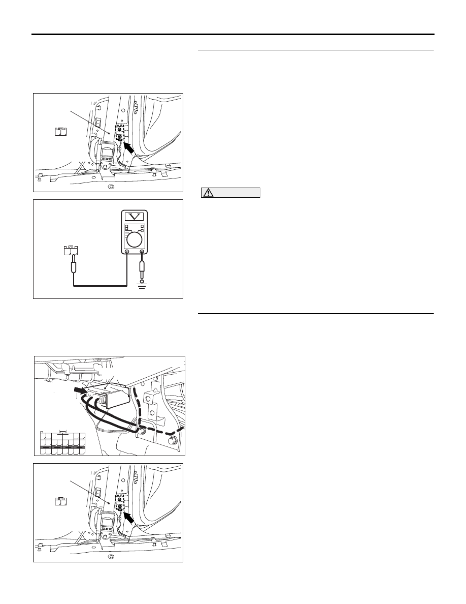
STEP 3. Check the side impact sensor (RH) power supply 
circuit. Measure the voltage at the side impact sensor (RH) 
connector D-35.
(1) Disconnect the negative battery terminal.
(2) Disconnect side impact sensor (RH) connector D-35, and 

measure at the wiring harness side.

(3) Connect the negative battery terminal.
(4) Turn the ignition switch to the "ON" position.

CAUTION

Do not insert a test probe into the terminal from its front 
side directly, as the connector contact pressure may be 
weakened.
(5) Measure the voltage between D-35 harness side connector 

terminal 2 and ground.
Voltage should measure 9 volts or more

Q: Is the measured voltage within the specified range?

YES : Replace the side impact sensor (RH) (Refer to 

P.52B-247

). Then go to Step 5.

NO :  Go to Step 4.

STEP 4. Check the harness wires for open circuit or short 
circuit between SRS-ECU connector D-26 (terminal No.63 
and 64) and side impact sensor (RH) connector D-35 
(terminal No.1 and 2).
Q: Are the harness wires between SRS-ECU connector 

D-26 (terminal No.63 and 64) and side impact sensor 
(RH) connector D-35 (terminal No.1 and 2) in good 
condition?
YES : 
Erase the diagnostic trouble code memory, and check 

the diagnostic trouble code. If DTC B1427 sets, 
replace the SRS-ECU (Refer to 

P.52B-234

). Then go 

to Step 5.

NO :  Replace the harness wires between SRS-ECU 

connector D-26 and side impact sensor (RH) 
connector D-35. Then go to Step 5.

AC308163

CONNECTOR: D-35

AC

FRONT SEAT BELT

2

1

HARNESS SIDE
CONNECTOR
(REAR VIEW)

AC201627

1 2

D-35 HARNESS SIDE
CONNECTOR
(REAR VIEW)

AQ

AC308163

CONNECTOR: D-35

AC

FRONT SEAT BELT

2

1

HARNESS SIDE
CONNECTOR
(REAR VIEW)

24DB063A

CONNECTOR: D-26

SRS-ECU

63

55

51

69

61

66

58

65

64

5657

68

60

67

59

70

62

53

52 B A

54

D-26  (Y)

D-26 FLOOR

HARNESS

CONNECTOR

(REAR VIEW)

SRS AIR BAG DIAGNOSIS

SUPPLEMENTAL RESTRAINT SYSTEM (SRS)

52B-117

STEP 5. Recheck for diagnostic trouble code.
Check again if the DTC is set.
(1) Erase the DTC.
(2) Turn the ignition switch to the "ON" position.
(3) Check if the DTC is set.
(4) Turn the ignition switch to the "LOCK" (OFF) position.

Q: Is DTC B1427 set?

YES : Return to Step 1.
NO :  The procedure is complete.

00DB076A

MB991910

DATA LINK

CONNECTOR

MB991824

MB991827

SRS AIR BAG DIAGNOSIS

SUPPLEMENTAL RESTRAINT SYSTEM (SRS)

52B-118

DTC B1428: Side-Impact sensor (RH) (Squib) for Power Supply Circuit
DTC B1429: Side-Impact sensor (RH) (Squib) for Communication System

CAUTION

If DTC B1428 or B1429 is set in the SRS-ECU, 
always diagnose the CAN main bus line.

.

CIRCUIT OPERATION

The side impact sensor includes an analog G sensor 
and CPU, etc. The CPU monitors the analog G sen-
sor output signal. If the CPU judges that the side-air-
bags should be deployed, it sends a fire signal to the 
SRS-ECU to deploy the side-airbags. In addition, the 
CPU diagnoses the internal components of the side 
impact sensor. If a malfunction occurs, it requests the 
SRS-ECU to set a diagnostic trouble code.

.

DTC SET CONDITIONS

These DTCs are set if communication between the 
side impact sensor (RH) and the SRS-ECU is not 
possible or communication is faulty.

.

TROUBLESHOOTING HINTS

• Damaged wiring harnesses or connectors

• Malfunction of the side impact sensor (RH)

• Malfunction of the SRS-ECU

• Refer to circuit diagrams GROUP-

90

• Refer to configuration diagrams GROUP-

80

.

DIAGNOSIS

Required Special Tool:

• MB991958: diagnostic tool (MUT-III Sub Assembly)

• MB991824: Vehicle Communication Interface (V.C.I.)

• MB991827: MUT-III USB Cable

• MB991910: MUT-III Main Harness A (Vehicles with CAN 

communication system)

24DB063A

CONNECTOR: D-26

SRS-ECU

63

55

51

69

61

66

58

65

64

5657

68

60

67

59

70

62

53

52 B A

54

D-26  (Y)

D-26 FLOOR

HARNESS

CONNECTOR

(REAR VIEW)

AC308163

CONNECTOR: D-35

AB

FRONT SEAT BELT

SRS AIR BAG DIAGNOSIS

SUPPLEMENTAL RESTRAINT SYSTEM (SRS)

52B-119

STEP 1. Using diagnostic tool MB991958, diagnose the 
CAN bus line.

CAUTION

To prevent damage to diagnostic tool MB991958, always 
turn the ignition switch to the "LOCK" (OFF) position 
before connecting or disconnecting diagnostic tool 
MB991958.
(1) Connect diagnostic tool MB991958. Refer to "How to 

connect the diagnostic tool 

P.52B-19

."

(2) Turn the ignition switch to the "ON" position.
(3) Diagnose the CAN bus line.
(4) Turn the ignition switch to the "LOCK" (OFF) position.

Q: Is the CAN bus line found to be normal?

YES : Go to Step 2.
NO :  Repair the CAN bus line (Refer to GROUP 54C, 

Diagnosis ).

STEP 2. Recheck for diagnostic trouble code.
Check again if the DTC is set.
(1) Erase the DTC.
(2) Turn the ignition switch to the "ON" position.
(3) Check if the DTC is set.
(4) Turn the ignition switch to the "LOCK" (OFF) position.

Q: Is the DTC set?

YES : Go to Step 3.
NO :  There is an intermittent malfunction such as poor 

engaged connector(s) or open circuit (Refer to 
GROUP 00, How to Use Troubleshooting/Inspection 
Service Points 

− How to Cope with Intermittent 

Malfunctions ).

00DB076A

MB991910

DATA LINK

CONNECTOR

MB991824

MB991827

00DB076A

MB991910

DATA LINK

CONNECTOR

MB991824

MB991827


Content   ..  796  797  798  799   ..