Mitsubishi 380. Manual - part 760
CYLINDER HEAD GASKET
TSB Revision
ENGINE MECHANICAL <3.8L ENGINE>
11A-42
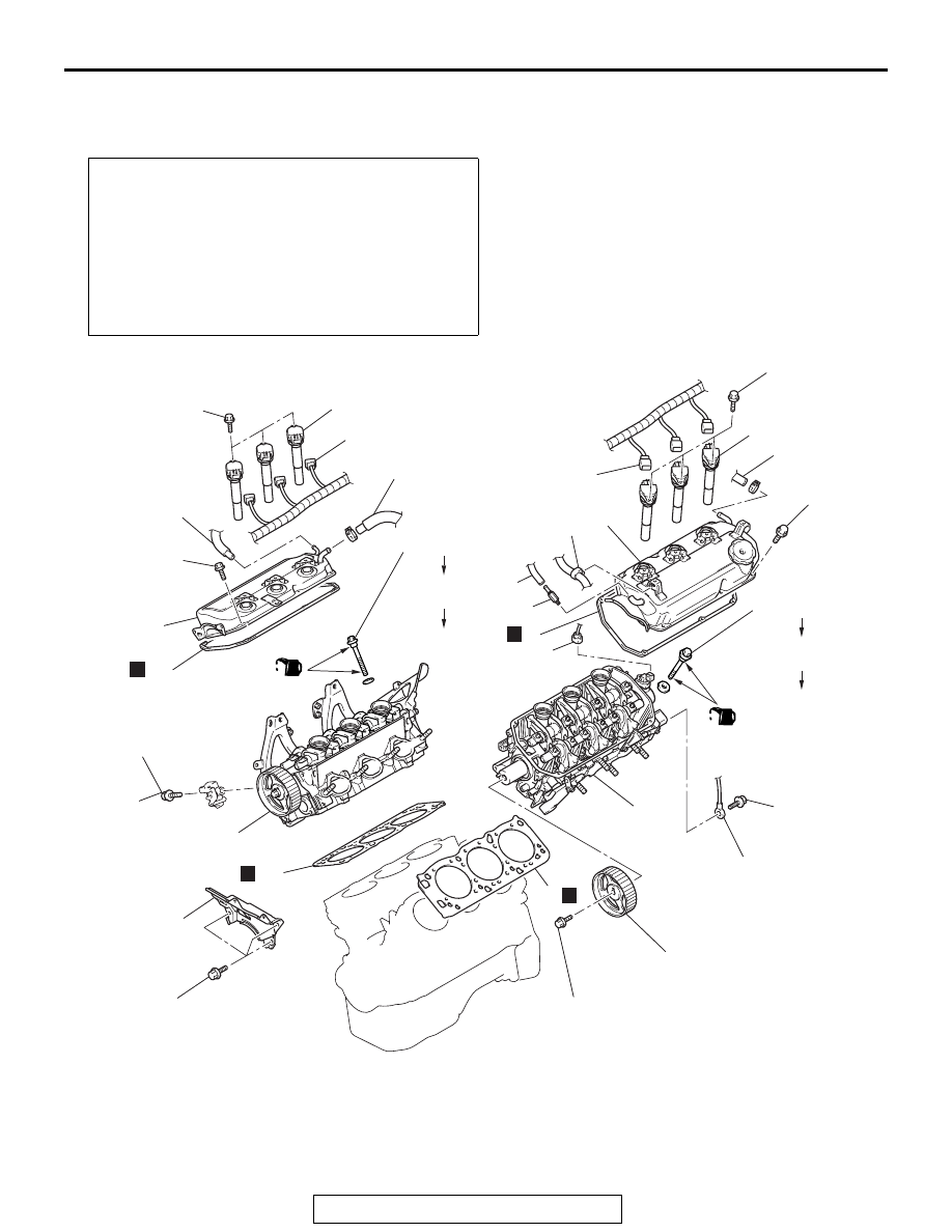
CYLINDER HEAD GASKET
REMOVAL AND INSTALLATION
M1112004000804
Pre-removal and Post-installation Operation
• Intake Manifold Removal and Installation (Refer to
• Exhaust Manifold Removal and Installation (Refer to
• Timing Belt Removal and Installation (Refer to
• Thermostat Housing Removal and Installation (Refer to
GROUP 14, Water Hose and Water Pipe
.)
• Generator Removal and Installation (Refer to GROUP 16,
Generator Assembly
.)
AC306788
<COLD ENGINE>
108 ± 5 N·m
80 ± 3 ft-lb
108 ± 5 N·m
80 ± 3 ft-lb
(ENGINE OIL)
<COLD ENGINE>
108 ± 5 N·m
80 ± 3 ft-lb
108 ± 5 N·m
80 ± 3 ft-lb
(ENGINE OIL)
3.5 ± 0.5 N·m
31 ± 4 in-lb
10 ± 2 N·m
89 ± 17 in-lb
10 ± 2 N·m
89 ± 17 in-lb
3.5 ± 0.5 N·m
31 ± 4 in-lb
22 ± 4 N·m
16 ± 3 ft-lb
88 ± 10 N·m
65 ± 7 ft-lb
41 ± 8 N·m
30 ± 6 ft-lb
14 ± 1 N·m
120 ± 13 in-lb
1
2
3
4
5
6
7
8
9
10
11
12
13
14
15
16
17
18
19
20
21
22
23
N
N
N
N
AB
0 N·m
0 in-lb
0 N·m
0 in-lb
REMOVAL STEPS
1.
BLOW-BY HOSE CONNECTION
2.
PCV HOSE CONNECTION
3.
PCV VALVE
4.
IGNITION COIL CONNECTOR
5.
IGNITION COIL
6.
ENGINE CONTROL WIRING
HARNESS CLAMP
7.
ROCKER COVER
8.
ROCKER COVER GASKET
REMOVAL STEPS (Continued)