Mitsubishi 380. Manual - part 723


  Index      Mitsubishi     Mitsubishi 380 - service repair manual 2005 year


Search            


Content   ..  721  722  723  724   ..


Mitsubishi 380. Manual - part 723


DIAGNOSIS

CONTROLLER AREA NETWORK (CAN)

54C-303

DIAGNOSIS

Required Special Tools:

• MB991223: Harness Set

• MB991219: Inspection Test Harness

• MB992045: A/T-ECU Check Harness

• MB992044: ENGINE-ECU Check Harness

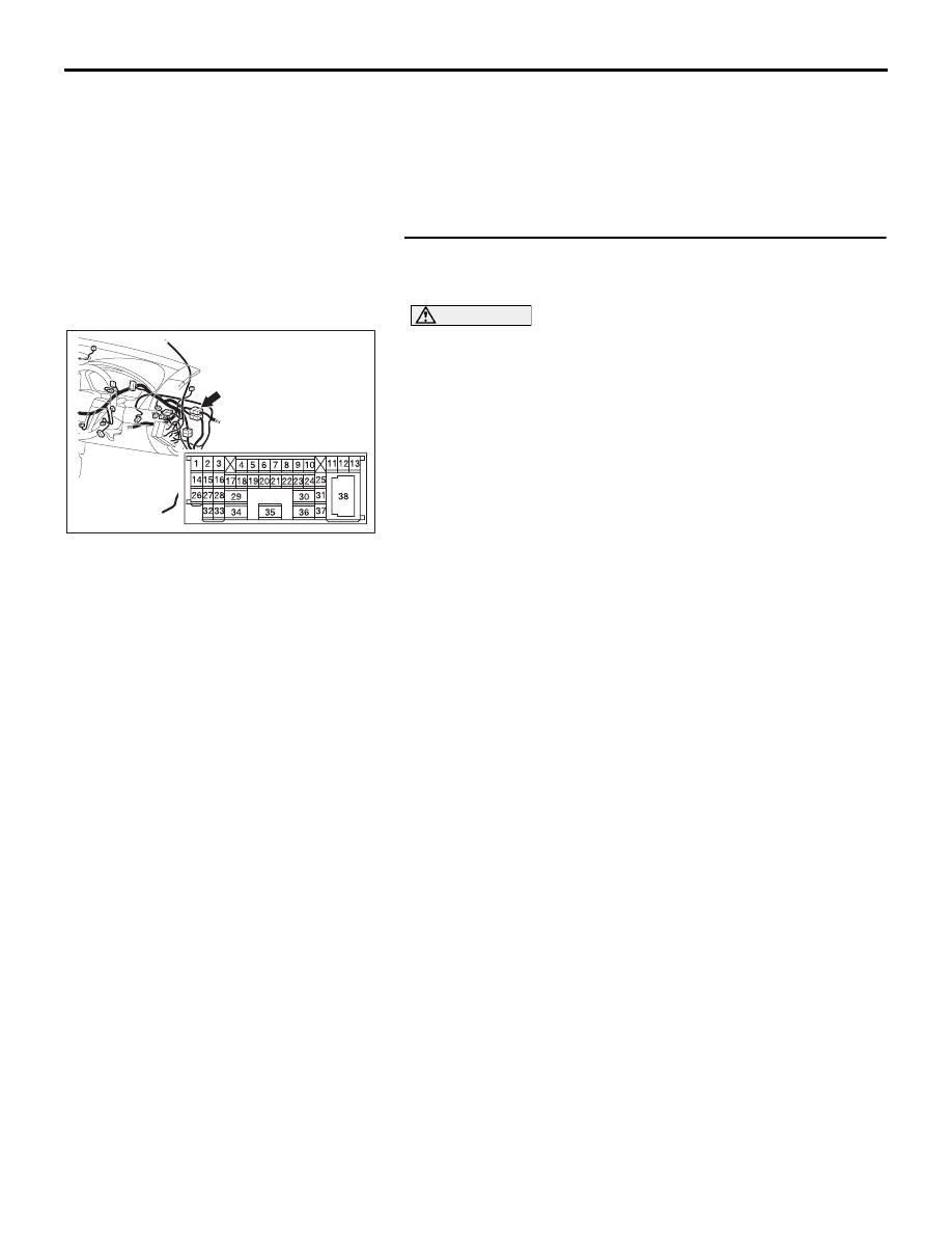
STEP 1. Check intermediate connector C-29 for loose, 
corroded or damaged terminals, or terminals pushed back 
in the connector.

CAUTION

The strand end of the twisted wire should be within 10 cm 
(4 inches) from the connector. For details refer to 

P.54C-4

.

Q: Is intermediate connector C-29 in good condition?

YES : Go to Step 2.
NO :  Repair the damaged parts.

52DB014A

CONNECTOR: C-29

DIAGNOSIS

CONTROLLER AREA NETWORK (CAN)

54C-304

STEP 2. Check the front wiring harness side CAN bus lines 
(communication line including the ENGINE-ECU). Measure 
the resistance at intermediate connector C-29.

CAUTION

A digital multimeter should be used. For details refer to 

P.54C-4

.

CAUTION

The test wiring harness should be used. For details refer to 

P.54C-4

.

(1) Disconnect intermediate connector C-29, and measure the 

resistance at the male side (at front wiring harness side).

(2) Turn the ignition switch to the "LOCK" (OFF) position.

CAUTION

Disconnect the negative battery terminal. For details refer 
to 

P.54C-4

.

(3) Disconnect the negative battery terminal.

(4) Measure the resistance between intermediate connector 

terminals 11 and 12.

OK: 120 

± 20 

Q: Does the resistance measure 120 

± 20 ?

YES : If the resistance measures 120 

± 20 Ω, go to Step 3.

NO :  If the resistance does not measure 120 

± 20 Ω, go to 

Step 7 .

52DB014A

CONNECTOR: C-29

AC204582

2 3

27

32

28

33

16

15

4 5

19

18

29

17

34

7 8

35

22

21

9 10

30

36

31

37

25

24

23

6

20

1

14

26

11

13

12

38

BX

TEST 
HARNESS

TEST 
HARNESS

MALE SIDE: C-29

DIAGNOSIS

CONTROLLER AREA NETWORK (CAN)

54C-305

STEP 3. Check joint connector (3) C-02 and combination 
meter connector C-101 for loose, corroded or damaged 
terminals, or terminals pushed back in the connector.

CAUTION

The strand end of the twisted wire should be within 10 cm 
(4 inches) from the connector. For details refer to 

P.54C-4

.

Check the joint connector at the wiring harness side for loose, 
corroded or damaged terminals, or terminals pushed back in 
the connector, and also check the short pin behind the connec-
tor for corrosion, deformation and delamination.

Q: Are joint connector (3) C-02 and combination meter 

connector C-101 in good condition?
YES : 
Go to Step 4.
NO :  Repair the damaged parts. Replace the joint 

connector as necessary.

16DB476A


HARNESS SIDE

C-101

CONNECTORS: C-02, C-101

C-02

C-02

C-101

AC209350

1

12

2

13

3

14

4

15

5

16

6

17

7

18

8

19

9

20

10

21

11
22

AB

SHORT PIN

DIAGNOSIS

CONTROLLER AREA NETWORK (CAN)

54C-306

STEP 4. Check the CAN bus lines (communication line 
including the combination meter) between joint connector 
(3) and the combination meter. Measure the resistance at 
joint connector (3) C-02.

CAUTION

A digital multimeter should be used. For details refer to 

P.54C-4

.

CAUTION

The test wiring harness should be used. For details refer to 

P.54C-4

.

(1) Disconnect joint connector (3) C-02, and measure the 

resistance at the wiring harness side of joint connector (3) 
C-02.

(2) Turn the ignition switch to the "LOCK" (OFF) position.

CAUTION

Disconnect the negative battery terminal. For details refer 
to 

P.54C-4

.

(3) Disconnect the negative battery terminal.

(4) Measure the resistance between joint connector (3) 

terminals 4 and 15.

OK: 120 

± 20 

Q: Does the resistance measure 120 

± 20 ?

YES : If the resistance measures 120 

± 20 Ω, diagnose CAN 

bus lines thoroughly by referring to 

P.54C-323

.

NO :  If the resistance does not measure 120 

± 20 Ω, go to 

Step 5 .

16DB408A

CONNECTOR: C-02

AC209438

11

22

10

21

9

20

8

19

7

18

6

17

5

16

4

15

3

14

2

13

1

12

TEST 
HARNESS

AQ

TEST 

HARNESS

HARNESS SIDE: C-02


Content   ..  721  722  723  724   ..