Mitsubishi 380. Manual - part 721


  Index      Mitsubishi     Mitsubishi 380 - service repair manual 2005 year


Search            


Content   ..  719  720  721  722   ..


Mitsubishi 380. Manual - part 721


DIAGNOSIS

CONTROLLER AREA NETWORK (CAN)

54C-295

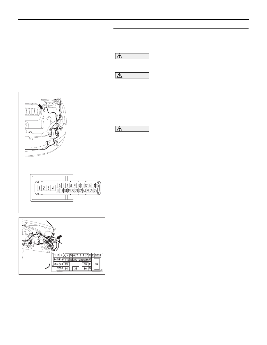
STEP 16. Check the CAN bus lines (communication line 
only) between intermediate connector C-29 and the 
ABS-ECU. Measure the resistance at intermediate 
connector C-29 and ABS-ECU connector A-02.

CAUTION

A digital multimeter should be used. For details refer to 

P.54C-4

.

CAUTION

The test wiring harness should be used. For details refer to 

P.54C-4

.

(1) Disconnect intermediate connector C-29 and ABS-ECU 

connector A-02, and measure the resistance between the 
wiring harness side connector of ABS-ECU connector A-02 
and the male side connector of intermediate connector 
C-29 (at front wiring harness side).

(2) Turn the ignition switch to the "LOCK" (OFF) position.

CAUTION

Disconnect the negative battery terminal. For details refer 
to 

P.54C-4

.

(3) Disconnect the negative battery terminal.

52DB014A

CONNECTOR: C-29

16DB402A

A-02 (GR)

CONNECTOR: A-02 

A-02 HARNESS CONNECTOR:

DIAGNOSIS

CONTROLLER AREA NETWORK (CAN)

54C-296

(4) Measure the resistance between intermediate connector 

terminal 11 and ABS-ECU connector terminal 25.

OK: 2 ohms or less

(5) Measure the resistance between intermediate connector 

terminal 12 and ABS-ECU connector terminal 14.

OK: 2 ohms or less

CAUTION

Strictly observe the specified wiring harness repair proce-
dure. For details refer to 

P.54C-5

.

Q: Do all the resistances measure 2 ohms or less?

YES : If all the resistances measure 2 ohms or less, go to 

Step 17.

NO :  If either of the resistances measures more than 2 

ohms or all the resistances measure more than 2 
ohms, repair the wiring harness between intermediate 
connector C-29 and the ABS-ECU connector, and 
then go to Step 8.

16DB513A

2 3

27

32

28

33

16

15

4 5

19

18

29

17

34

7 8

35

22

21

9 10

30

36

31

37

25

24

23

6

20

1

14

26

11

13

12

38

TEST
HARNESS

TEST
HARNESS

HARNESS SIDE: A-02

MALE SIDE: C-29

16DB514A

2 3

27

32

28

33

16

15

4 5

19

18

29

17

34

7 8

35

22

21

9 10

30

36

31

37

25

24

23

6

20

1

14

26

11

13

12

38

TEST 
HARNESS

TEST 
HARNESS

HARNESS SIDE: A-02

MALE SIDE: C-29

DIAGNOSIS

CONTROLLER AREA NETWORK (CAN)

54C-297

STEP 17. Check the ABS-ECU for open circuit. Measure 
the resistance at ABS-ECU connector A-02.

CAUTION

A digital multimeter should be used. For details refer to 

P.54C-4

.

(1) Disconnect ABS-ECU connector A-02, and measure the 

resistance at the component side of ABS-ECU connector 
A-02.

(2) Measure the resistance between ABS-ECU connector 

terminals 14 and 15.

OK: 2 ohms or less

(3) Measure the resistance between ABS-ECU connector 

terminals 25 and 26.

OK: 2 ohms or less

Q: Do all the resistances measure 2 ohms or less?

YES : If all the resistances measure 2 ohms or less, go to 

Step 8.

NO :  If either of the resistances measures more than 2 

ohms or all the resistances measure more than 2 
ohms, replace the ABS-ECU.

16DB402A

A-02 (GR)

CONNECTOR: A-02 

A-02 HARNESS CONNECTOR:

16DB515A

COMPONENT SIDE: A-02

TEST 
HARNESS

TEST 
HARNESS

16DB516A

COMPONENT SIDE: A-02

TEST 
HARNESS

TEST 
HARNESS

DIAGNOSIS

CONTROLLER AREA NETWORK (CAN)

54C-298

STEP 18. Check the A/T-ECU for open circuit. Measure the 
resistance at A/T-ECU connector B-19.

NOTE: when diagnosing CAN-BUS on vehicles with 
manual transmission (M/T), disregard A/T-ECU and it’s wir-
ing circuits and check between ABS-ECU and 
ENGINE-ECU only.

• Refer to circuit diagrams GROUP-

90

• Refer to configuration diagrams GROUP-

80

CAUTION

A digital multimeter should be used. For details refer to 

P.54C-4

.

(1) Disconnect A/T-ECU connector B-19, and measure the 

resistance at the component side of A/T-ECU connector 
B-19.

(2) Measure the resistance between A/T-ECU connector B-19 

terminals 14 and 5.

OK: 2 ohms or less

(3) Measure the resistance between A/T-ECU connector B-19 

terminals 13 and 4.

OK: 2 ohms or less

Q: Do all the resistances measure 2 ohms or less?

YES : If all the resistances measure 2 ohms or less, go to 

Step 8.

NO :  If either of the resistances measures more than 2 

ohms or all the resistances measure more than 2 
ohms, replace the A/T-ECU.

16DB480A

COVER

ENGINE

CONTROL

UNIT

AIR

CLEANER

A/T

CONTROL

UNIT

16DB518A

TEST
HARNESS

TEST
HARNESS

COMPONENT SIDE:  B-19

16DB519A

TEST
HARNESS

TEST
HARNESS

COMPONENT SIDE:  B-19


Content   ..  719  720  721  722   ..