Mitsubishi 380. Manual - part 663


  Index      Mitsubishi     Mitsubishi 380 - service repair manual 2005 year


Search            


Content   ..  661  662  663  664   ..


Mitsubishi 380. Manual - part 663


DIAGNOSIS

CONTROLLER AREA NETWORK (CAN)

54C-63

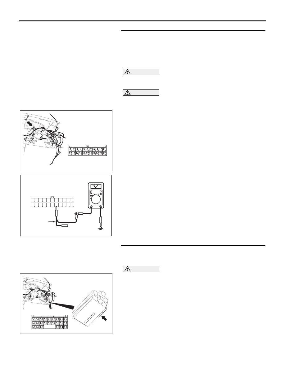
STEP 31. Check the CAN_L line (communication line 
including the ETACS-ECU) between joint connector (3) and 
the ETACS-ECU connector for a short to the power supply. 
Measure the voltage at joint connector (3) C-02.

• Refer to circuit diagrams GROUP-

90

• Refer to configuration diagrams GROUP-

80

CAUTION

A digital multimeter should be used. For details refer to 

P.54C-4

.

CAUTION

The test wiring harness should be used. For details refer to 

P.54C-4

.

(1) Disconnect joint connector (3) C-02, and measure the 

voltage at the wiring harness side of joint connector (3) 
C-02.

(2) Turn the ignition switch to the "ON" position.

(3) Measure the voltage between joint connector (3) terminal 

16 and body ground.

OK: 4.0 V or less

Q: Does the voltage measure 4.0 V or less?

YES : If the voltage measures 4.0 V or less, go to Step 34.
NO :  If the voltage measures more than 4.0 V, go to Step 

32.

STEP 32. Check ETACS-ECU connector C-218 for loose, 
corroded or damaged terminals, or terminals pushed back 
in the connector.

CAUTION

The strand end of the twisted wire should be within 10 cm 
(4 inches) from the connector. For details refer to 

P.54C-4

.

Q: Is ETACS-ECU connector C-218 in good condition?

YES : Go to Step 33.
NO :  Repair the damaged parts.

16DB408A

CONNECTOR: C-02

AC209365

11

22

10

21

9

20

8

19

7

18

6

17

5

16

4

15

3

14

2

13

1

12

AC209365

AC209365GC

HARNESS SIDE: C-02

TEST 
HARNESS

16DB474A

C-218 (GR)

CONNECTOR: C-218

HARNESS SIDE

JUNCTION BLOCK
(REAR VIEW)

DIAGNOSIS

CONTROLLER AREA NETWORK (CAN)

54C-64

STEP 33. Check the CAN_L line (communication line only) 
between joint connector (3) and ETACS-ECU connector for 
a short to the power supply. Measure the voltage at joint 
connector (3) C-02.

CAUTION

A digital multimeter should be used. For details refer to 

P.54C-4

.

CAUTION

The test wiring harness should be used. For details refer to 

P.54C-4

.

(1) Disconnect joint connector (3) C-02 and ETACS-ECU 

connector C-218, and measure the voltage at the wiring 
harness side of joint connector (3) C-02.

(2) Turn the ignition switch to the "ON" position.

(3) Measure the voltage between joint connector (3) terminal 

16 and body ground.

OK: 1.0 V or less

CAUTION

Strictly observe the specified wiring harness repair proce-
dure. For details refer to 

P.54C-5

.

Q: Does the voltage measure 1.0 V or less?

YES : If the voltage measures 1.0 V or less, diagnose CAN 

bus lines thoroughly by referring to 

P.54C-323

.

NO :  If the voltage measures more than 1.0 V, repair the 

wiring harness between joint connector (3) and the 
ETACS-ECU connector.

16DB408A

CONNECTOR: C-02

16DB474A

C-218 (GR)

CONNECTOR: C-218

HARNESS SIDE

JUNCTION BLOCK
(REAR VIEW)

AC209365

11

22

10

21

9

20

8

19

7

18

6

17

5

16

4

15

3

14

2

13

1

12

AC209365

AC209365GC

HARNESS SIDE: C-02

TEST 
HARNESS

DIAGNOSIS

CONTROLLER AREA NETWORK (CAN)

54C-65

STEP 34. Check the CAN_L line (communication line 
including the A/C-ECU) between joint connector (3) and 
the A/C-ECU connector for a short to the power supply. 
Measure the voltage at joint connector (3) C-02.

CAUTION

A digital multimeter should be used. For details refer to 

P.54C-4

.

CAUTION

The test wiring harness should be used. For details refer to 

P.54C-4

.

(1) Disconnect joint connector (3) C-02, and measure the 

voltage at the wiring harness side of joint connector (3) 
C-02.

(2) Turn the ignition switch to the "ON" position.

(3) Measure the voltage between joint connector (3) terminal 

17 and body ground.

OK: 4.0 V or less

Q: Does the voltage measure 4.0 V or less?

YES : If the voltage measures 4.0 V or less, go to Step 37.
NO :  If the voltage measures more than 4.0 V, go to Step 

35.

16DB408A

CONNECTOR: C-02

AC209365

11

22

10

21

9

20

8

19

7

18

6

17

5

16

4

15

3

14

2

13

1

12

AC209365

AC209365GD

HARNESS SIDE: C-02

TEST 
HARNESS

DIAGNOSIS

CONTROLLER AREA NETWORK (CAN)

54C-66

STEP 35. Check A/C-ECU connector C-15 automatic air 
conditioning system for loose, corroded or damaged 
terminals, or terminals pushed back in the connector.

CAUTION

The strand end of the twisted wire should be within 10 cm 
(4 inches) from the connector. For details refer to 

P.54C-4

.

Q: Is A/C-ECU connector  C-15 automatic air conditioning 

system in good condition?
YES : 
Go to Step 36.
NO :  Repair the damaged parts.

16DB477A

C-15 HARNESS SIDE

CONNECTOR:  C-15

C-15 (B)


Content   ..  661  662  663  664   ..