Mitsubishi 380. Manual - part 645
INJECTOR
MULTIPORT FUEL INJECTION (MPI) <3.8L ENGINE>
13A-672
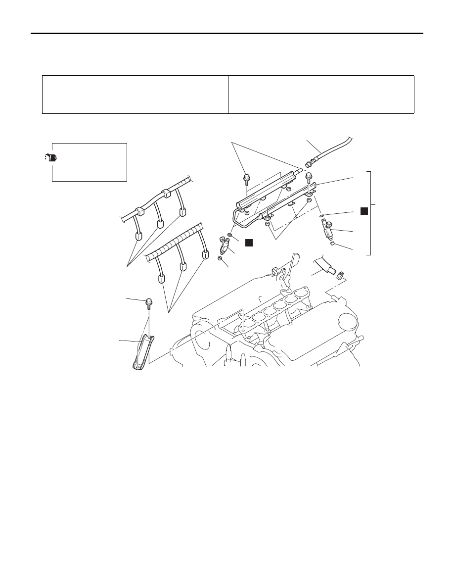
INJECTOR
REMOVAL AND INSTALLATION
M1131007100768
Pre-removal Operation
• Fuel Discharge Prevention (Refer to
).
• Intake Manifold Plenum Removal (Refer to GROUP 15,
Intake Manifold Plenum
Post-installation Operation
• Intake Manifold Plenum Installation (Refer to GROUP 15,
Intake Manifold Plenum
• Fuel Leakage Inspection.
03DB144A
1
1
3
6
5
10
9
8
7
11
N
2
12 ± 1 N·m
102 ± 13 in-lb
9
8
7
N
APPLY ENGINE OIL
TO ALL MOVING
PARTS BEFORE
INSTALLATION.
36 ± 6 N·m
27 ± 4 ft-lb
REMOVAL STEPS
1.
INJECTOR CONNECTOR
2.
ENGINE MOUNT STAY
>>A<<
3.
FUEL HIGH-PRESSURE HOSE
CONNECTION (FUEL RAIL SIDE)
5.
BLOW-BY HOSE CONNECTION
<<A>>
6.
FUEL RAIL AND INJECTOR
ASSEMBLY
7.
INSULATORS
>>A<<
8.
FUEL INJECTORS
>>A<<
9.
O-RING
10. FUEL RAIL
11. INSULATORS
REMOVAL STEPS (Continued)