Mitsubishi 380. Manual - part 643


  Index      Mitsubishi     Mitsubishi 380 - service repair manual 2005 year


Search            


Content   ..  641  642  643  644   ..


Mitsubishi 380. Manual - part 643


ON-VEHICLE SERVICE

MULTIPORT FUEL INJECTION (MPI) <3.8L ENGINE>

13A-664

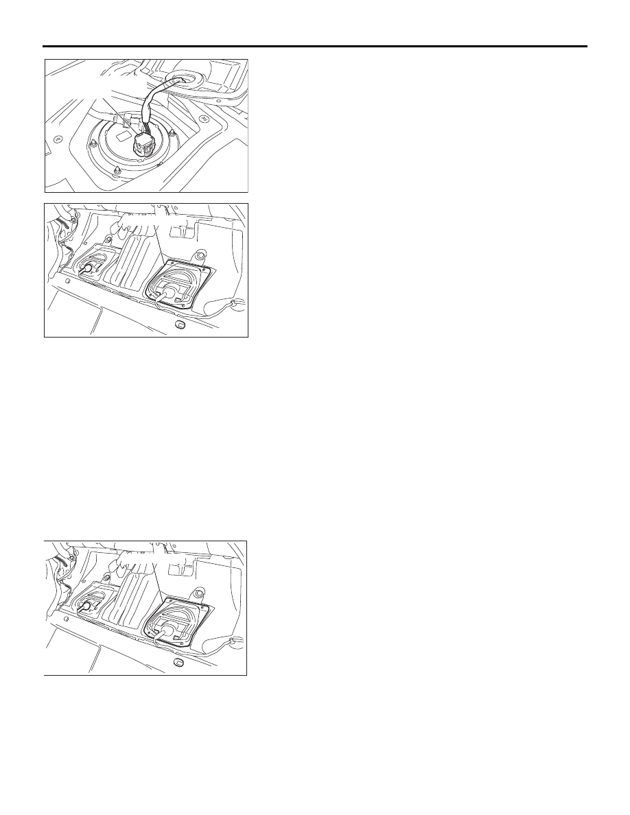
3. Disconnect the fuel pump module connector.

4. After starting the engine and letting it run until it stops 

naturally, turn the ignition switch to the "LOCK" (OFF) 
position.

5. Connect the fuel pump module connector.

6. Install the hole cover (LHS).

Tightening torque: 1.5 

± 0.5 Nm (14 ± 4 in-lb)

7. Install the rear seat cushion assembly (Refer to GROUP 

52A, Rear Seat Assembly 

P.52A-55

).

FUEL PUMP OPERATION CHECK

M1131002000692

1. If the fuel pump will not operate, check by using the 

following procedure. If normal, check the fuel pump drive 
circuit.

(1) Turn the ignition switch to "ON". Listen for fuel pump 

running for approximately 2 seconds. Pump will 
automatically stop after this time.

NOTE: As the fuel pump is an in-tank type, the fuel pump 
sound is hard to hear. Remove the fuel tank filler tube cap 
and check from the tank inlet.

(2) Remove the rear seat cushion assembly (Refer to 

GROUP 52A, Rear Seat 

P.52A-55

).

(3) Remove the hole cover (LHS).

AC306490

FUEL PUMP MODULE
CONNECTOR

AB

03DB150A

HOLE COVER

03DB150A

HOLE COVER

ON-VEHICLE SERVICE

MULTIPORT FUEL INJECTION (MPI) <3.8L ENGINE>

13A-665

(4) Disconnect the fuel pump module connector.

(5) Attach 12 Volt supply to fuel pump, terminal no. 4 to earth 

and terminal no.5 to power. Check if the sound of the fuel 
pump operation can be heard. If no operating sound is 
heard, replace the fuel pump module (Refer to GROUP 
13B, On-vehicle Service 

− Fuel Pump Module 

Replacement 

P.13B-6

).

NOTE: As the fuel pump is an in-tank type, the fuel pump 
sound is hard to hear. Remove the fuel tank filler tube cap 
and check from the tank inlet.

(6) Check for fuel pressure by pinching the fuel hose with 

fingertips.

(7) Connect the fuel pump module connector.
(8) Install the hole cover (LHS).

Tightening torque: 1.5 

± 0.5 Nm (14 ± 4 in-lb)

(9) Install the rear seat cushion assembly (Refer to GROUP 

52A, Rear Seat Assembly 

P.52A-55

).

AC306490

FUEL PUMP MODULE
CONNECTOR

AB

1 2 3

4 5

AC305681

03DB150A

HOLE COVER

ON-VEHICLE SERVICE

MULTIPORT FUEL INJECTION (MPI) <3.8L ENGINE>

13A-666

MULTIPORT FUEL INJECTION (MPI) RELAY  
CONTINUITY CHECK

M1131050000345

Inspect the MPI relay relay for continuity in accordance with the 
chart shown below.

FUEL PUMP RELAY CONTINUITY CHECK

M1131033000342

Inspect the fuel pump relay for continuity in accordance with 
the chart shown below.

BATTERY 
VOLTAGE

TERMINAL NO. 
TO BE 
CONNECTED TO 
BATTERY

TERMINAL NO. 
TO BE 
CONDUCTED

Not supplied

− 3

Supplied

−  3

− 4

03DB258A

1 2
3 4

1 2
3 4

MPI RELAY  

SIDE CONNECTOR

MPI RELAY

SIDE CONNECTOR

BATTERY 
VOLTAGE

TERMINAL NO. 
TO BE 
CONNECTED TO 
BATTERY

TERMINAL NO. 
TO BE 
CONDUCTED

Not supplied

− 3

Supplied

−  3

− 4

1 2

3

2

3 4

1

4

AK302122

FUEL PUMP RELAY

SIDE CONNECTOR

FUEL PUMP RELAY

SIDE CONNECTOR

AB

ON-VEHICLE SERVICE

MULTIPORT FUEL INJECTION (MPI) <3.8L ENGINE>

13A-667

INTAKE AIR TEMPERATURE SENSOR CHECK

M1131002800557

1. Disconnect the mass airflow sensor connector.(Refer to 

GROUP 15, Air Cleaner, Removal and Installation 

P.15-4

)

2. Measure resistance between terminals 1 and 3.

Standard value:

12.66 

 15.12 k [at -20°C (-4°F)]

5.119 

 5.892 k [at 0°C (32°F)]

2.290 

 2.551 k [at 20°C (68°F)]

1.096 

 1.258 k [at 40°C (104°F)]

0.565 

 0.654 k [at 60°C (140°F)]

0.312 

 0.370 k [at 80°C (176°F)]

3. If not within specifications, replace the mass airflow sensor.
4. Measure resistance while heating the sensor using a hair 

dryer.

Normal condition:

5. If resistance does not decrease as heat increases, replace 

the mass airflow sensor.

CAUTION

Do not remove Air Temperature Sensor unit from the  
housing. If sensor is faulty replace complete Air Flow Sen-
sor assembly.

ENGINE COOLANT TEMPERATURE SENSOR 
CHECK

M1131003100528

CAUTION

Be careful not to touch the connector (resin section) with 
the tool when removing and installing.
1. Drain engine coolant, then remove the engine coolant 

temperature sensor.

2. With the temperature sensing portion of engine coolant 

temperature sensor immersed in hot water, check the 
resistance.

Standard value:

14 

 17 k [at -20°C (-4°F)]

5.5 

 6.3 k [at 0°C (32°F)]

2.35 

 2.65 k [at 20°C (68°F)]

1.12 

 1.23 k [at 40°C (104°F)]

0.573 

 0.618 k [at 60°C (140°F)]

0.313 

 0.332 k [at 80°C (176°F)]

TEMPERATURE

RESISTANCE (k

)

Higher

Smaller

03DB158A

INTAKE AIR TEMPERATURE

SENSOR CONNECTOR

03DB177A

MASS AIRFLOW 

SENSOR

AKX01622


Content   ..  641  642  643  644   ..