Mitsubishi 380. Manual - part 640
MULTIPORT FUEL INJECTION (MPI) DIAGNOSIS
MULTIPORT FUEL INJECTION (MPI) <3.8L ENGINE>
13A-652
INSPECTION PROCEDURE USING AN
OSCILLOSCOPE
M1131154501085
CAMSHAFT POSITION SENSOR AND
CRANKSHAFT POSITION SENSOR
Required Special Tools:
• MB992044: ECU Check Harness
.
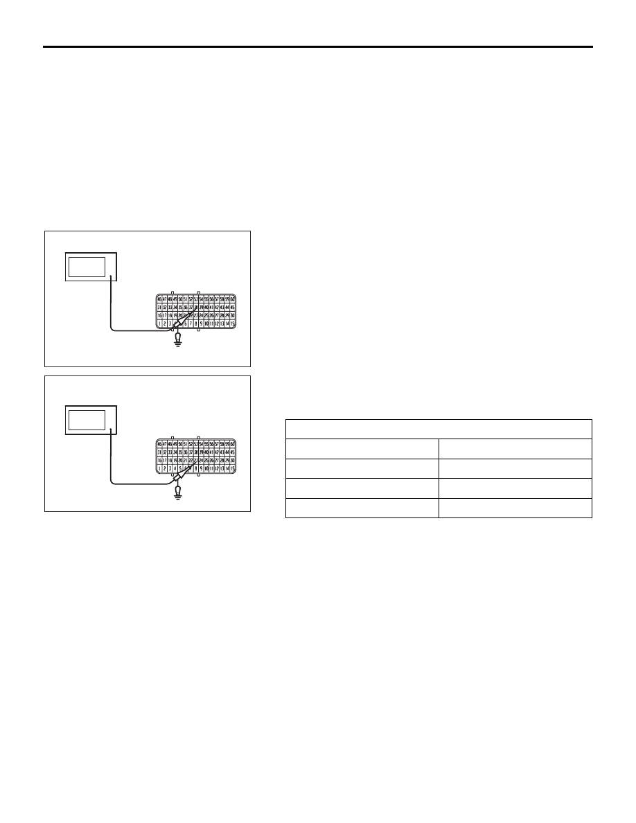
Measurement Method
1. Disconnect the all ECU connectors, and connect check
harness special tool (MB992044) between the separated
connectors.
2. Connect the oscilloscope to check harness terminal No. 38.
(Check the camshaft position sensor signal wave pattern.)
3. Connect the oscilloscope to check harness terminal No. 23.
(Check the crankshaft position sensor signal wave pattern.)
Standard Wave Pattern
Observation condition
Function
Special pattern
Pattern height
Low
Pattern selector
Display
Engine r/min
Idle speed
03DB243A
B-20 HARNESS
CONNECTOR
OSCILLOSCOPE
03DB244A
B-20 HARNESS
CONNECTOR
OSCILLOSCOPE