Mitsubishi 380. Manual - part 633
MULTIPORT FUEL INJECTION (MPI) DIAGNOSIS
MULTIPORT FUEL INJECTION (MPI) <3.8L ENGINE>
13A-624
INSPECTION PROCEDURE 26: Ignition Switch-ST System and Transmission Inhibitor Switch System
.
COMMENT
• If the selector lever is moved to "P" or "N" range
and the ignition switch is turned to "START" posi-
tion, battery positive voltage is supplied to ECU
(terminal No. 9) through the ignition switch and
transmission inhibitor switch. Because of this, the
ECU detects that the engine is cranking.
• The transmission inhibitor switch detects the
transmission inhibitor (P, N or other ranges) and
converts it to a voltage signal (high or low). Then
the transmission inhibitor switch sends that signal
to the ECU.
If the selector lever is moved to "P" or "N" range
with the ignition switch turned on (except
"START" position), continuity will exist between
the ECU and ground through the transmission
inhibitor switch and starter motor. The terminal
voltage of the ECU will become low. If the selec-
tor lever is moved to the other ranges, continuity
will be lost between the ECU and ground. The
terminal voltage of the ECU will become high.
.
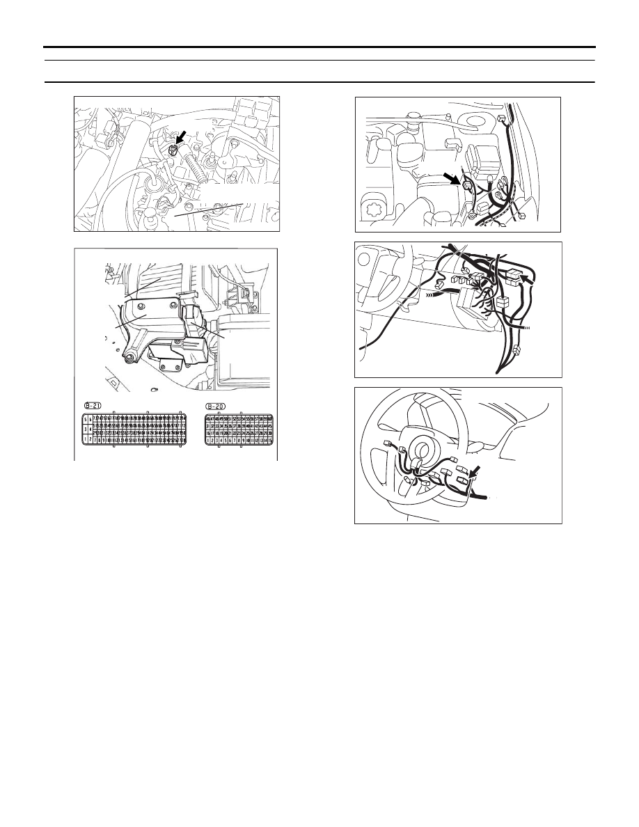
AK303268AB
TRANSMISSION
RANGE SWITCH
CONNECTOR: B-110
B-110 (B)
16DB400A
COVER
ENGINE
CONTROL
UNIT
AIR
CLEANER
AK303148
CONNECTOR: A-13
AB
A-13(GR)
03DB171A
CONNECTOR: C-29
C-29
03DB170A
CONNECTOR: C-308
C-308