Mitsubishi 380. Manual - part 631


  Index      Mitsubishi     Mitsubishi 380 - service repair manual 2005 year


Search            


Content   ..  629  630  631  632   ..


Mitsubishi 380. Manual - part 631


MULTIPORT FUEL INJECTION (MPI) DIAGNOSIS

MULTIPORT FUEL INJECTION (MPI) <3.8L ENGINE>

13A-616

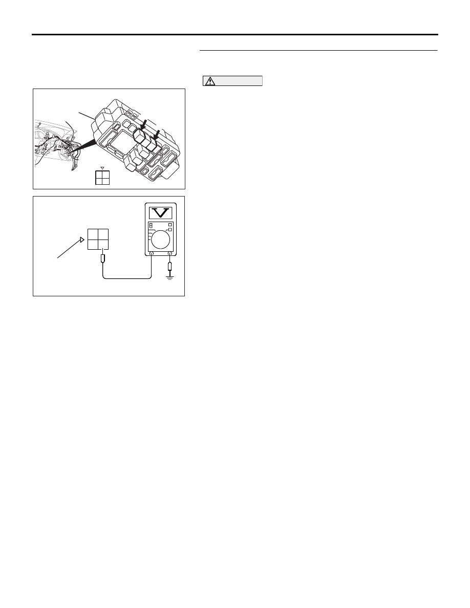
STEP 4. Measure the power supply voltage at fuel pump 
relay 1 harness side connector C-210.

CAUTION

Because it is difficult to distinguish the top and bottom of 
the fuel pump relay connector at the wiring harness, 
inspect it by using the triangle mark on the junction block 
as a reference.
(1) Disconnect the connector C-210 and measure at the 

harness side.

(2) Measure the voltage between terminal No. 4 and ground.

• Voltage should measure battery positive voltage.

Q: Is battery positive voltage (approximately 12 volts) 

present?
YES : 
Go to Step 5.
NO :  Check harness connector C-214 at intermediate 

connector for damage, and repair or replace as 
required. Refer to, GROUP 00E, Harness Connector 
Inspection 

P.00E-2

. If intermediate connector is in 

good condition, repair harness wire between relay 
box and fuel pump relay 1 connector C-210 (terminal 
No. 4) because of open circuit. Then confirm that the 
malfunction symptom is eliminated.

03DB166A

CONNECTOR: C-208, C-210

JUNCTION

BLOCK

HARNESS 

CONNECTOR

C-208

C-210

3

4

1

2

3

4

1

2

1 3

4

2

AK203269

C-210 HARNESS 

CONNECTOR: 

COMPONENT SIDE

AB

JUNCTION

BLOCK

TRIANGLE

MARK

MULTIPORT FUEL INJECTION (MPI) DIAGNOSIS

MULTIPORT FUEL INJECTION (MPI) <3.8L ENGINE>

13A-617

STEP 5. Measure the power supply voltage at fuel pump 
relay 1 harness side connector C-210.

CAUTION

Because it is difficult to distinguish the top and bottom of 
the fuel pump relay connector at the wiring harness, 
inspect it by using the triangle mark on the junction block 
as a reference.
(1) Disconnect the connector C-210 and measure at the 

harness side.

(2) Turn the ignition switch to the "ON" position.

(3) Measure the voltage between terminal No. 3 and ground.

• Voltage should be battery positive voltage.

(4) Turn the ignition switch to the "LOCK" (OFF) position.

Q: Is battery positive voltage (approximately 12 volts) 

present?
YES : 
Go to Step 6.
NO :  Check harness connector C-215 at intermediate 

connector for damage, and repair or replace as 
required. Refer to, GROUP 00E, Harness Connector 
Inspection 

P.00E-2

. If intermediate connector is in 

good condition, repair harness wire between ignition 
switch connector C-308 (terminal No. 2) and fuel 
pump relay 1 connector C-210 (terminal No. 3) 
because of open circuit. Then confirm that the 
malfunction symptom is eliminated.

03DB166A

CONNECTOR: C-208, C-210

JUNCTION

BLOCK

HARNESS 

CONNECTOR

C-208

C-210

3

4

1

2

3

4

1

2

1 3

4

2

AK203270

C-210 HARNESS 

CONNECTOR: 

COMPONENT SIDE

AB

JUNCTION

BLOCK

TRIANGLE

MARK

MULTIPORT FUEL INJECTION (MPI) DIAGNOSIS

MULTIPORT FUEL INJECTION (MPI) <3.8L ENGINE>

13A-618

STEP 6. Check for continuity at fuel pump relay 1 harness 
side connector C-210.

CAUTION

Because it is difficult to distinguish the top and bottom of 
the fuel pump relay connector at the wiring harness, 
inspect it by using the triangle mark on the junction block 
as a reference.
(1) Disconnect the connector C-210 and measure at the 

harness side.

(2) Check for the continuity between terminal No. 2 and 

ground.

• Should be less than 2 ohms.

Q: Does continuity exist?

YES : Go to Step 7.
NO :  Check connector C-211 at intermediate connector for 

damage, and repair or replace as required. Refer to 
GROUP 00E, Harness Connector Inspection 

P.00E-2

. If intermediate connector is in good 

condition, repair harness wire between fuel pump 
relay 1 connector C-210 (terminal No. 2) and ground 
because of open circuit. Then confirm that the 
malfunction symptom is eliminated.

03DB166A

CONNECTOR: C-208, C-210

JUNCTION

BLOCK

HARNESS 

CONNECTOR

C-208

C-210

3

4

1

2

3

4

1

2

1 3

4

2

AK203271

C-210 HARNESS 

CONNECTOR: 

COMPONENT SIDE

JUNCTION

BLOCK

TRIANGLE

MARK

AB

MULTIPORT FUEL INJECTION (MPI) DIAGNOSIS

MULTIPORT FUEL INJECTION (MPI) <3.8L ENGINE>

13A-619

STEP 7. Measure the power supply voltage at fuel pump 
relay 2 harness side connector C-208.

CAUTION

Because it is difficult to distinguish the top and bottom of 
the fuel pump relay connector at the wiring harness, 
inspect it by using the triangle mark on the junction block 
as a reference.
(1) Disconnect the connector C-208 and measure at the 

harness side.

(2) Turn the ignition switch to the "ON" position.

(3) Measure the voltage between terminal No. 1 and ground.

• Voltage should be battery positive voltage.

Q: Is battery positive voltage (approximately 12 volts) 

present?
YES : 
Go to Step 8.
NO :  Repair harness wire between fuel pump relay 1 

connector C-210 (terminal No. 1) and fuel pump relay 
2 connector C-208 (terminal No. 1) because of open 
circuit. Then confirm that the malfunction symptom is 
eliminated.

3

4

1

2

3
4

1

2

3
4

1

2

03DB167A

JUNCTION BLOCK

C-208

HARNESS CONNECTOR:

COMPONENT SIDE

CONNECTOR: C-208

2 1

3

4

AK203273

C-208 HARNESS 

CONNECTOR: 

COMPONENT SIDE

AB

JUNCTION

BLOCK

TRIANGLE

MARK


Content   ..  629  630  631  632   ..