Mitsubishi 380. Manual - part 626


  Index      Mitsubishi     Mitsubishi 380 - service repair manual 2005 year


Search            


Content   ..  624  625  626  627   ..


Mitsubishi 380. Manual - part 626


MULTIPORT FUEL INJECTION (MPI) DIAGNOSIS

MULTIPORT FUEL INJECTION (MPI) <3.8L ENGINE>

13A-596

STEP 3. Check the advance ignition timing.
Ignition timing is controlled by the ENGIN-ECUand will vary 
depending on engine requirement..

Q: Is the advance ignition timing normal?

YES : Go to Step 4.
NO :  Check that the crankshaft position sensor and timing 

belt cover are in the correct position. Then confirm 
that the malfunction symptom is eliminated. 

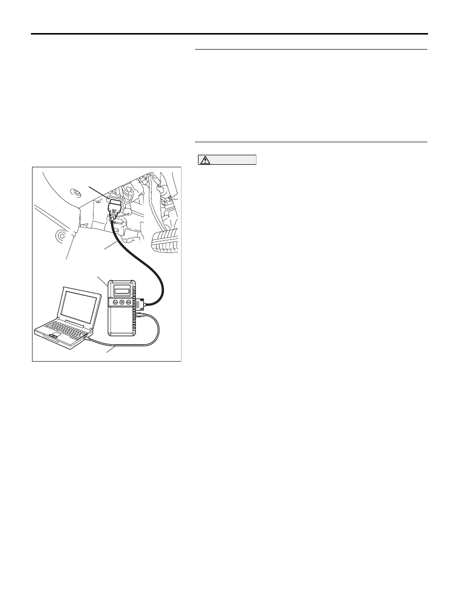
STEP 4. Using diagnostic tool, check data list.

CAUTION

To prevent damage to diagnostic tool, always turn the igni-
tion switch to the "LOCK" (OFF) position before connect-
ing or disconnecting diagnostic tool.
(1) Connect diagnostic tool to the data link connector.
(2) Turn the ignition switch to the "ON" position.
(3) Check the following items in the data list. Refer to Data List 

Reference Table 

P.13A-637

.

a. Item 05: Intake Air Temperature Sensor.
b. Item 06: Engine Coolant Temperature Sensor.

c. Item AD: Right Bank Heated Oxygen Sensor (rear).

d. Item AC: Right Bank Heated Oxygen Sensor (front).
e. Item AF: Left Bank Heated Oxygen Sensor (rear).

f. Item AE: Left Bank Heated Oxygen Sensor (front).

(4) Turn the ignition switch to the "LOCK" (OFF) position.

Q: Are they operating properly?

YES : Go to Step 5.
NO :  Repair or replace it. Then confirm that the malfunction 

symptom is eliminated.

00DB076A

MB991910

DATA LINK

CONNECTOR

MB991824

MB991827

MULTIPORT FUEL INJECTION (MPI) DIAGNOSIS

MULTIPORT FUEL INJECTION (MPI) <3.8L ENGINE>

13A-597

STEP 5. Using diagnostic tool, check data list.
(1) Turn the ignition switch to the "ON" position.
(2) Check the following items of data list. Refer to Data List 

Reference Table 

P.13A-637

.

a. Item AC: Right Bank Heated Oxygen Sensor (front).
b. Item AE: Left Bank Heated Oxygen Sensor (front).

• Voltage should fluctuate between 0 − 0.4 volt and 0.6 − 

1.0 volt while idling after the engine has been warmed.

(3) Turn the ignition switch to the "LOCK" (OFF) position.

Q: Are they operating properly?

YES : Go to Step 7.
NO :  Go to Step 6.

STEP 6. Check the fuel pressure.
Refer to On-vehicle Service 

− Fuel Pressure Test 

P.13A-661

.

Q: Is the fuel pressure normal?

YES : Check the following items, and repair or replace the 

defective items.

a. Vacuum leak.

• Broken intake manifold gasket.

• Broken air intake hose.

• Broken vacuum hose.

• Positive crankcase ventilation valve does 

not operate.

b. Injector clogged.

Then confirm that the malfunction symptom is 

eliminated.

NO :  Repair or replace it. Then confirm that the malfunction 

symptom is eliminated.

STEP 7. Check the fuel pressure.
Refer to On-vehicle Service 

− Fuel Pressure Test 

P.13A-661

.

Q: Is the fuel pressure normal?

YES : Check the following items, and repair or replace the 

defective items.

a. Check the ignition coil and spark plugs.

Then confirm that the malfunction symptom is 

eliminated.

NO :  Repair or replace it. Then confirm that the malfunction 

symptom is eliminated.

00DB076A

MB991910

DATA LINK

CONNECTOR

MB991824

MB991827

MULTIPORT FUEL INJECTION (MPI) DIAGNOSIS

MULTIPORT FUEL INJECTION (MPI) <3.8L ENGINE>

13A-598

INSPECTION PROCEDURE 20: Knocking

.

COMMENT

• Incase such as the above, the cause is probably 

that the detonation control is defective or the heat 
value of the spark plug is inappropriate.

.

TROUBLESHOOTING HINTS (The most 
likely causes for this case:)

• Defective knock sensor.

• Incorrect heat value of the spark plug.

• Refer to component locations GROUP-

70

• Refer to configuration diagrams GROUP-

80

• Refer to circuit diagrams GROUP-

90

DIAGNOSIS

Required Special Tools:

• Diagnostic tool(MUT-III Sub Assembly)

• MB991824: V.C.I.

• MB991827: USB Cable

• MB991910: Main Harness A

STEP 1. Using the diagnostic tool, read the diagnostic 
trouble code (DTC).

CAUTION

To prevent damage to diagnostic tool, always turn the igni-
tion switch to the "LOCK" (OFF) position before connect-
ing or disconnecting diagnostic tool.
(1) Connect diagnostic tool to the data link connector.
(2) Turn the ignition switch to the "ON" position.
(3) Read the DTC.
(4) Turn the ignition switch to the "LOCK" (OFF) position.

Q: Is the DTC set?

YES : Refer to Diagnostic Trouble Code Chart 

P.13A-17

.

NO :  Go to Step 2.

00DB076A

MB991910

DATA LINK

CONNECTOR

MB991824

MB991827

MULTIPORT FUEL INJECTION (MPI) DIAGNOSIS

MULTIPORT FUEL INJECTION (MPI) <3.8L ENGINE>

13A-599

STEP 2. Check Data list, Item No. 16 advance ignition 
timing. 
(1) The advance ignition timing should retard more when knock 

sensor connector B-120 is disconnected than when it is 
connected.

Q: When the knock sensor connector B-120 was 

disconnected, was the advance ignition timing delayed? 
YES : 
Check the following items, and repair or replace the 

defective items.

a. Check the spark plugs.
b. Fuel quality, octane level.

c. Check if the foreign materials (water, 

kerosene, etc.) got into fuel.

Then confirm that the malfunction symptom is 

eliminated.

NO :  Refer to DTC P0325 

− Knock Sensor Circuit 

P.13A-346

.

INSPECTION PROCEDURE 21: Dieseling (Run-on).

.

COMMENT

• Fuel leakage from injectors is suspected, or car-

bon build up.

.

TROUBLESHOOTING HINTS (The most 
likely causes for this case:)

• Fuel leakage from injectors.

DIAGNOSIS

Replace the leaking injector. Then confirm that the malfunction 
symptom is eliminated.

AK303120

1

2

KNOCK SENSOR

AB

CONNECTOR: B-120

B-120 (GR)

HARNESS

CONNECTOR:

COMPONENT SIDE


Content   ..  624  625  626  627   ..