Mitsubishi 380. Manual - part 604


  Index      Mitsubishi     Mitsubishi 380 - service repair manual 2005 year


Search            


Content   ..  602  603  604  605   ..


Mitsubishi 380. Manual - part 604


MULTIPORT FUEL INJECTION (MPI) DIAG

MULTIPORT FUEL INJECTION (MPI)

13A-508

STEP 7. Replace the accelerator pedal position sensor.
(1) Replace the accelerator pedal position sensor.
(2) Turn the ignition switch to the "ON" position.
(3) After the DTC has been deleted, read the DTC again.
(4) Turn the ignition switch to the "LOCK" (OFF) position.

Q: Is DTC P2128 set?

YES : Then go to Step 8.
NO :  The inspection is complete.

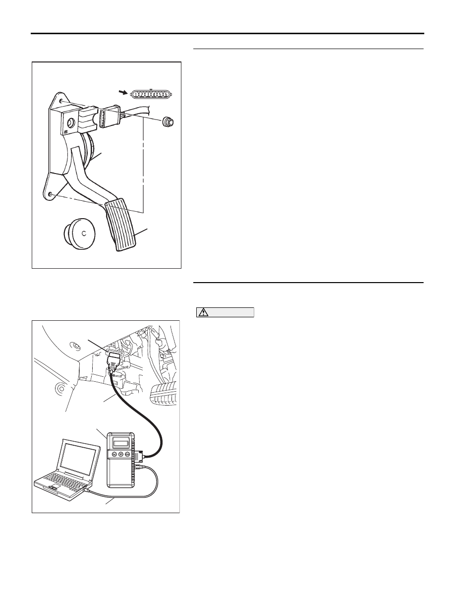
STEP 8. Using diagnostic tool , check data list item 12: 
Accelerator Pedal Position Sensor (sub).

CAUTION

To prevent damage to diagnostic tool , always turn the 
ignition switch to the "LOCK"(OFF) position before con-
necting or disconnecting diagnostic tool .
(1) Connect diagnostic tool to the data link connector.
(2) Turn the ignition switch to the "ON" position.
(3) Set diagnostic tool to the data reading mode for


item 12, 

Accelerator Pedal Position Sensor (sub).

• Output voltage is between 0435 and 1035 mV when foot 

is released from accelerator pedal.

• Output voltage is between 4000 - 4824 mV when accel-

erator pedal is fully depressed.

(4) Turn the ignition switch to the "LOCK"(OFF) position.

Q: Is the sensor operating properly?

YES : It can be assumed that this malfunction is intermittent. 

Refer to GROUP 00, How to Use 
Troubleshooting/Inspection Service Points 

− How to 

Cope with Intermittent Malfunctions 

P.00-14

.

NO :  Then go to Step 9.

ACCELERATOR
PEDAL

CONNECTOR: C-24

C-24 (B)

ACCELERATOR 
PEDAL POSITION 
SENSOR

HARNESS
CONNECTOR:
COMPONENT SIDE

16DB562A

00DB076A

MB991910

DATA LINK

CONNECTOR

MB991824

MB991827

MULTIPORT FUEL INJECTION (MPI) DIAG

MULTIPORT FUEL INJECTION (MPI)

13A-509

STEP 9. Using diagnostic tool , read the diagnostic trouble 
code (DTC).
(1) Connect diagnostic tool to the data link connector.
(2) Turn the ignition switch to the "ON" position.
(3) After the DTC has been deleted, read the DTC again.
(4) Turn the ignition switch to the "LOCK"(OFF) position.

Q: Is DTC P2128 set?

YES : Retry the troubleshooting.
NO :  The inspection is complete.

00DB076A

MB991910

DATA LINK

CONNECTOR

MB991824

MB991827

MULTIPORT FUEL INJECTION (MPI) DIAG

MULTIPORT FUEL INJECTION (MPI)

13A-510

DTC P2135: Throttle Position Sensor (Main and Sub) Range/Performance Problem

.

THROTTLE POSITION SENSOR (MAIN 
AND SUB) RANGE/PERFORMANCE 
PROBLEM CIRCUIT

• Refer to DTC P0122 − Throttle Position Sensor 

(Main) Circuit 

P.13A-148

.

• Refer to DTC P0222 − Throttle Position Sensor 

(Sub) Circuit 

P.13A-318

.

.

CIRCUIT OPERATION

• Refer to DTC P0122 − Throttle Position Sensor 

(Main) Circuit 

P.13A-148

.

• Refer to DTC P0222 − Throttle Position Sensor 

(Sub) Circuit 

P.13A-318

.

.

TECHNICAL DESCRIPTION

• ENGINE-ECU checks the throttle position sensor 

output signal characteristics for abnormal condi-
tions.

.

Check Conditions

• Ignition switch is "ON" position.

• Battery voltage is above 6.5 volt.

Judgement Criteria

• Throttle angle variances are outside specifica-

tions.

• MIL activated immediately.

• Engine speed limited to 1200rpm and power 

restricted.

.

EOBD DRIVE CYCLE PATTERN

None.

.

TROUBLESHOOTING HINTS (The most 
likely causes for this code to be set are:)

• Throttle position sensor failed.

• Shorted throttle position sensor circuit or connec-

tor damage.

• Refer to component locations GROUP-

70

• Refer to configuration diagrams GROUP-

80

• Refer to circuit diagrams GROUP-

90

DIAGNOSIS

Required Special Tools:

• : Diagnostic tool (MUT-III Sub Assembly)

• MB991824: V.C.I.

• MB991827: USB Cable

• MB991910: Main Harness A

MULTIPORT FUEL INJECTION (MPI) DIAG

MULTIPORT FUEL INJECTION (MPI)

13A-511

STEP 1. Check harness connector B-06 at throttle position 
sensor and harness connector B-20 at ENGINE-ECU for 
damage.
Q: Is the harness connector in good condition?

YES : Go to Step 2.
NO :  Repair or replace it. Refer to GROUP 00E, Harness 

Connector Inspection 

P.00E-2

. Then go to Step 5.

03DB180A

CONNECTOR: B-06

B-06 (B)

16DB400A

COVER

ENGINE

CONTROL

UNIT

AIR

CLEANER


Content   ..  602  603  604  605   ..