Mitsubishi 380. Manual - part 570
MULTIPORT FUEL INJECTION (MPI) DIAGNOSIS
MULTIPORT FUEL INJECTION (MPI)
13A-372
13A
DTC P0340: Camshaft Position Sensor Circuit.
.
CIRCUIT OPERATION
• The camshaft position sensor power is supplied
from the ECU (terminal No. 25).
• Terminal No. 3 of the camshaft position sensor is
grounded with ECU (terminal No. 8).
• A 5-volt supply is applied to the camshaft position
sensor output terminal (terminal No. 2) from the
ECU (terminal No. 38). The camshaft position
sensor generates a pulse signal when the output
terminal is opened and grounded.
.
TECHNICAL DESCRIPTION
• The camshaft position sensor functions to detect
the top dead center position of the number 1 cyl-
inder and to convert that data to pulse signals
that are input to the ECU.
• When the engine is running, the camshaft posi-
tion sensor outputs a pulse signal.
• The ECU checks whether pulse signal is input
while the engine is cranking.
.
DTC SET CONDITIONS <Range/Performance problem - Alignment>
Check Conditions
• Engine speed is higher than 50 r/min.
Judgment Criteria
• Normal signal pattern has not been input for cyl-
inder identification from the crankshaft position
sensor signal and camshaft position sensor sig-
nal for 2 seconds.
• MIL activated immediately.
• Engine stalls.
.
DTC SET CONDITIONS <Range/Performance problem - Circuit continuity>
Check Conditions
• Engine speed is higher than 50 r/min.
Judgment Criteria
• Camshaft position sensor output voltage has not
changed (no pulse signal is input) for 2 seconds.
• MIL activated immediately.
• Engine stalls.
.
EOBD DRIVE CYCLE PATTERN
Refer to Diagnostic Function
− EOBD Drive Cycle −
.
.
TROUBLESHOOTING HINTS (The most
likely causes for this code to be set are: )
• Camshaft position sensor failed.
• Open or shorted camshaft position sensor circuit.
• Harness or connector damage.
• Refer to component locations GROUP-
AK303129AB
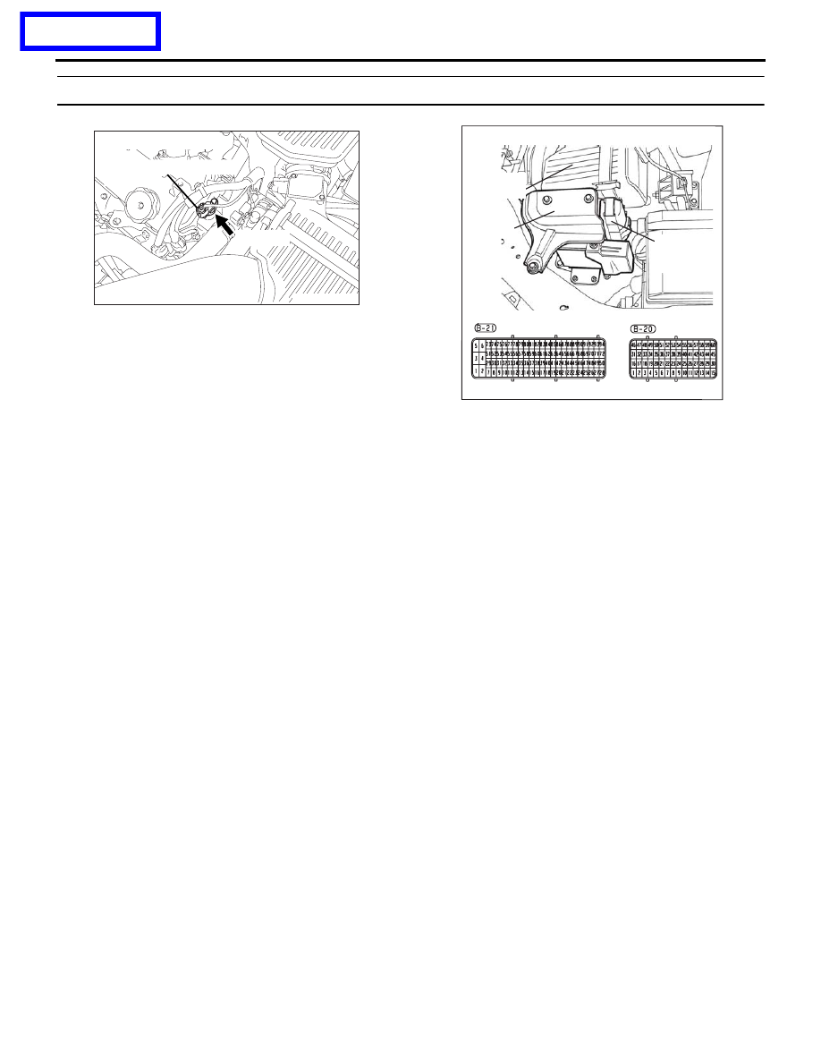
CAMSHAFT POSITION
SENSOR
B-106 (B)
CONNECTOR: B-106
16DB400A
COVER
ENGINE
CONTROL
UNIT
AIR
CLEANER