Mitsubishi 380. Manual - part 521


  Index      Mitsubishi     Mitsubishi 380 - service repair manual 2005 year


Search            


Content   ..  519  520  521  522   ..


Mitsubishi 380. Manual - part 521


MULTIPORT FUEL INJECTION (MPI) DIAGNOSIS

MULTIPORT FUEL INJECTION (MPI)

13A-176

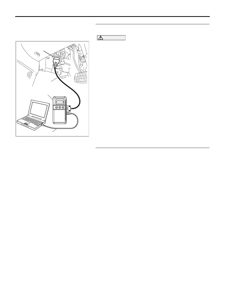
STEP 4. Using diagnostic tool, check data list item AC: 
Heated Oxygen Sensor Bank 1, Sensor 1 (right front).

CAUTION

To prevent damage to diagnostic tool, always turn the igni-
tion switch to the "LOCK" (OFF) position before connect-
ing or disconnecting diagnostic tool .
(1) Connect diagnostic tool  to the data link connector.
(2) Start the engine and run at idle.
(3) Ensure engine is at running temperature (80

° C or higher).

(4) Set diagnostic tool  to the data reading mode for item AC, 

Heated Oxygen Sensor Bank 1, Sensor 1 (right front).

(5) Warm up the engine, hold at 2,500 r/min.

• Output voltage alternates between 0.1 volt and 0.6 − 1.0 

volt 10 times or more within 10 seconds.

(6) Turn the ignition switch to the "LOCK" (OFF) position.

NOTE: If data list readings are consistantly low or appear 
slow to cycle( should cycle every 0.5-1.0 sec.) during check 
the sensor is likely to be malfuctioning. 

Q: Is the sensor operating properly?

YES : It can be assumed that this malfunction is intermittent. 

Refer to GROUP 00, How to Use 
Troubleshooting/Inspection Service Points 

− How to 

Cope with Intermittent Malfunctions 

P.00-14

.

NO :  Replace the sensor. Then go to Step 5.

STEP 5. Test the EOBD drive cycle.
(1) Carry out a test drive with the drive cycle pattern. Refer to 

Diagnostic Function 

− EOBD Drive Cycle − 

P.13A-11

.

(2) Check the diagnostic trouble code (DTC).

Q: Is DTC P0132 set?

YES : Retry the troubleshooting.
NO :  The inspection is complete.

00DB076A

MB991910

DATA LINK

CONNECTOR

MB991824

MB991827

MULTIPORT FUEL INJECTION (MPI) DIAGNOSIS

MULTIPORT FUEL INJECTION (MPI)

13A-177

DTC P0133: Heated Oxygen Sensor Circuit Slow Response (bank 1, sensor 1).

.

CIRCUIT OPERATION

• A voltage corresponding to the oxygen concen-

tration in the exhaust gas is sent to the 
ENGINE-ECU (terminal No. 45) from the output 
terminal (terminal No. 1) of the right bank heated 
oxygen sensor (front).

• Terminal No. 2 of the right bank heated oxygen 

sensor (front) is grounded with ENGINE-ECU 
(terminal No. 44).

.

TECHNICAL DESCRIPTION

• The right bank heated oxygen sensor (front) 

detects the concentration of oxygen in the 
exhaust gas; it converts those data to voltage, 
and inputs the resulting signals to the 
ENGINE-ECU.

• When the right bank heated oxygen sensor 

(front) begins to deteriorate, the heated oxygen 
sensor signal response becomes poor.

• The ENGINE-ECU forcibly varies the air/fuel mix-

ture to make it leaner and richer, and checks the 
response speed of the right bank heated oxygen 
sensor (front). In addition, the ENGINE-ECU also 
checks for an open circuit in the right bank 
heated oxygen sensor (front) output line.

.

DTC SET CONDITIONS

Check Conditions

• Engine speed between 1320 and 3200rpm.

Judgment Criteria

• MIL is activated after 2 Drive cycles.

• No limp home.

.

EOBD DRIVE CYCLE PATTERN

Refer to Diagnostic Function 

− EOBD Drive Cycle − 

P.13A-11

.

.

TROUBLESHOOTING HINTS (The most 
likely causes for this code to be set are: )

• Right bank heated oxygen sensor (front) deterio-

rated.

• Refer to component locations GROUP-

70

• Refer to configuration diagrams GROUP-

80

• Refer to circuit diagrams GROUP-

90

DIAGNOSIS

Required Special Tools:

• : Diagnostic Tool (MUT-III Sub Assembly)

• MB991824: V.C.I.

AK303047

B-09 (B)

CONNECTOR: B-09

THROTTLE BODY

RIGHT BANK

HEATED OXYGEN

SENSOR (FRONT)

AB

16DB400A

COVER

ENGINE

CONTROL

UNIT

AIR

CLEANER

MULTIPORT FUEL INJECTION (MPI) DIAGNOSIS

MULTIPORT FUEL INJECTION (MPI)

13A-178

• MB991827: USB Cable

• MB991910: Main Harness A

STEP 1. Using diagnostic tool, check data list item AC: 
Heated Oxygen Sensor Bank 1, Sensor 1 (right front).

CAUTION

To prevent damage to diagnostic tool, always turn the igni-
tion switch to the "LOCK" (OFF) position before connect-
ing or disconnecting diagnostic tool .
(1) Connect diagnostic tool  to the data link connector.
(2) Start the engine and run at idle.
(3) Ensure engine is at running temperature (80

° C or higher).

(4) Set diagnostic tool  to the data reading mode for item AC, 

Heated Oxygen Sensor Bank 1, Sensor 1 (right front).

(5) Warm up the engine, hold at 2,500 r/min.

• Output voltage alternates between 0.1 volt and 0.6 − 1.0 

volt 10 times or more within 10 seconds.

(6) Turn the ignition switch to the "LOCK" (OFF) position.

NOTE: If data list readings are consistantly low or appear 
slow to cycle( should cycle every 0.5-1.0 sec.) during check 
the sensor is likely to be malfuctioning. 

Q: Is the sensor operating properly?

YES : It can be assumed that this malfunction is intermittent. 

Refer to GROUP 00, How to Use 
Troubleshooting/Inspection Service Points 

− How to 

Cope with Intermittent Malfunctions 

P.00-14

.

NO :  Replace the sensor. Then go to Step 2.

STEP 2. Test the EOBD drive cycle.
(1) Carry out a test drive with the drive cycle pattern. Refer to 

Diagnostic Function 

− EOBD Drive Cycle − 

P.13A-11

.

(2) Check the diagnostic trouble code (DTC).

Q: Is DTC P0133 set?

YES : Retry the troubleshooting.
NO :  The inspection is complete.

00DB076A

MB991910

DATA LINK

CONNECTOR

MB991824

MB991827

MULTIPORT FUEL INJECTION (MPI) DIAGNOSIS

MULTIPORT FUEL INJECTION (MPI)

13A-179

DTC P0134: Heated Oxygen Sensor Circuit No Activity Detected (bank 1, sensor 1).

CAUTION

If DTC P0134 has been set, TCL related DTC 
U1120 is also set. After P0134 has been diag-
nosed, don't forget to erase DTC U1120.

.

CIRCUIT OPERATION

• A voltage corresponding to the oxygen concen-

tration in the exhaust gas is sent to the 
ENGINE-ECU (terminal No. 45) from the output 
terminal (terminal No. 1) of the right bank heated 
oxygen sensor (front).

• Terminal No. 2 of the right bank heated oxygen 

sensor (front) is grounded with ENGINE-ECU 
(terminal No. 44).

.

TECHNICAL DESCRIPTION

• The right bank heated oxygen sensor (front) 

detects the concentration of oxygen in the 
exhaust gas; it converts those data to voltage, 
and inputs the resulting signals to the 
ENGINE-ECU.

• When the right bank heated oxygen sensor 

(front) begins to deteriorate, the heated oxygen 
sensor signal response becomes poor.

• The ENGINE-ECU forcibly varies the air/fuel mix-

ture to make it leaner and richer, and checks the 
response speed of the right bank heated oxygen 
sensor (front). In addition, the ENGINE-ECU also 
checks for an open circuit in the right bank 
heated oxygen sensor (front) output and ground 
lines.

.

DTC SET CONDITIONS

Check Conditions

• Battery voltage < 11.02 volts

• Engine coolant temperature is higher than 80°C. 

Judgment Criteria

• MIL is activated after 2 Drive cycles.

• No limp home.

.

EOBD DRIVE CYCLE PATTERN

Refer to Diagnostic Function 

− EOBD Drive Cycle − 

P.13A-11

.

.

TROUBLESHOOTING HINTS (The most 
likely causes for this code to be set are: )

• Right bank heated oxygen sensor failed.

• Open circuit in right bank heated oxygen sensor 

(front) output line.

• Open circuit in right bank heated oxygen sensor 

(front) sensor ground.

• Wiring harness or connector damage.

• Refer to component locations GROUP-

70

• Refer to configuration diagrams GROUP-

80

• Refer to circuit diagrams GROUP-

90

DIAGNOSIS

Required Special Tools:

• : Diagnostic Tool (MUT-III Sub Assembly)

• MB991824: V.C.I.

• MB991827: USB Cable

• MB991910: Main Harness A

• MB992044:  ENGINE-ECU Check Harness


Content   ..  519  520  521  522   ..