Mitsubishi 380. Manual - part 520


  Index      Mitsubishi     Mitsubishi 380 - service repair manual 2005 year


Search            


Content   ..  518  519  520  521   ..


Mitsubishi 380. Manual - part 520


MULTIPORT FUEL INJECTION (MPI) DIAGNOSIS

MULTIPORT FUEL INJECTION (MPI)

13A-172

DTC P0132: Heated Oxygen Sensor Circuit High Voltage (bank 1, sensor 1).

.

CIRCUIT OPERATION

• A voltage corresponding to the oxygen concen-

tration in the exhaust gas is sent to the 
ENGINE-ECU (terminal No. 45) from the output 
terminal (terminal No. 1) of the right bank heated 
oxygen sensor (front).

• Terminal No. 2 of the right bank heated oxygen 

sensor (front) is grounded with ENGINE-ECU 
(terminal No. 44).

.

TECHNICAL DESCRIPTION

• The right bank heated oxygen sensor (front) 

detects the concentration of oxygen in the 
exhaust gas; it converts those data to voltage, 
and inputs the resulting signals to the 
ENGINE-ECU.

• When the right bank heated oxygen sensor 

(front) begins to deteriorate, the heated oxygen 
sensor signal response becomes poor.

• The ENGINE-ECU forcibly varies the air/fuel mix-

ture to make it leaner and richer, and checks the 
response speed of the right bank heated oxygen 
sensor (front). In addition, the ENGINE-ECU also 
checks for an open circuit in the right bank 
heated oxygen sensor (front) output line.

.

DTC SET CONDITIONS

Check Conditions

• Battery voltage < 11.02 volts

• Engine coolant temperature is higher than 80°C. 

Judgment Criteria

• Internal Resistance of the Nernst - cell is equal or 

greater than a modelled resistance based on the 
heating output of the O2-sensor and the mod-
elled exhasused gas temperature.

• Idling.

• MIL is activated after 2 Drive cycles.

• No limp home.

.

EOBD DRIVE CYCLE PATTERN

Refer to Diagnosis Function 

− EOBD Drive Cycle − 

P.13A-11

.

.

TROUBLESHOOTING HINTS (The most 
likely causes for this code to be set are: )

• Short circuit to battery voltage in right bank 

heated oxygen sensor (front) output line.

• Wiring harness or connector damage.

• Refer to component locations GROUP-

70

• Refer to configuration diagrams GROUP-

80

• Refer to circuit diagrams GROUP-
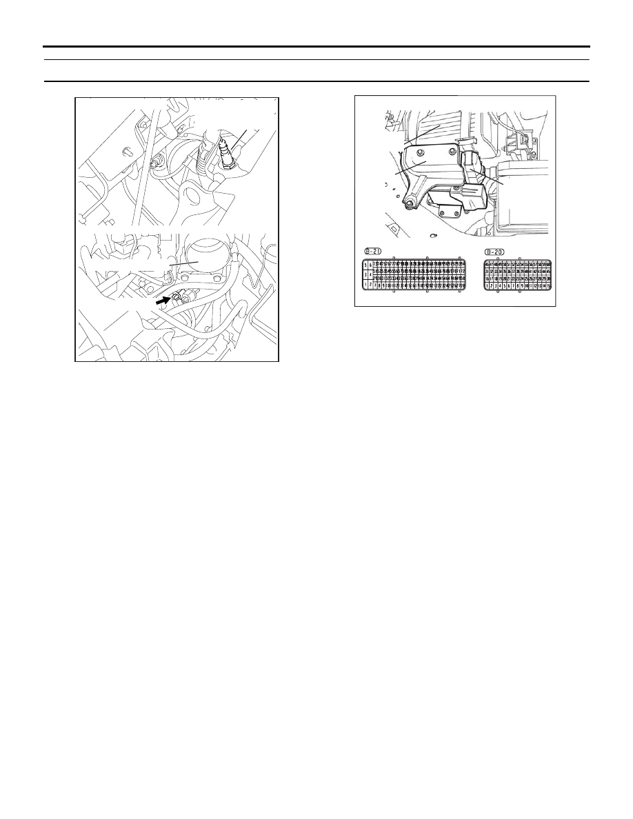
90

AK303047

B-09 (B)

CONNECTOR: B-09

THROTTLE BODY

RIGHT BANK

HEATED OXYGEN

SENSOR (FRONT)

AB

16DB400A

COVER

ENGINE

CONTROL

UNIT

AIR

CLEANER

MULTIPORT FUEL INJECTION (MPI) DIAGNOSIS

MULTIPORT FUEL INJECTION (MPI)

13A-173

DIAGNOSIS

STEP 1. Using diagnostic tool, check data list item AC: 
Heated Oxygen Sensor Bank 1, Sensor 1 (right front).

CAUTION

To prevent damage to diagnostic tool, always turn the igni-
tion switch to the "LOCK" (OFF) position before connect-
ing or disconnecting diagnostic tool .
(1) Connect diagnostic tool  to the data link connector.
(2) Start the engine and run at idle.
(3) Ensure engine is at running temperature (80

° C or higher).

(4) Set diagnostic tool  to the data reading mode for item AC, 

Heated Oxygen Sensor Bank 1, Sensor 1 (right front).

(5) Warm up the engine, hold at 2,500 r/min.

• Output voltage alternates between 0.1 volt and 0.6 − 1.0 

volt 10 times or more within 10 seconds.

(6) Turn the ignition switch to the "LOCK" (OFF) position.

NOTE: If data list readings are consistantly low or appear 
slow to cycle( should cycle every 0.5-1.0 sec.) during check 
the sensor is likely to be malfuctioning. 

Q: Is the sensor operating properly?

YES : It can be assumed that this malfunction is intermittent. 

Refer to GROUP 00, How to Use 
Troubleshooting/Inspection Service Points 

− How to 

Cope with Intermittent Malfunctions 

P.00-14

.

NO :  Then go to Step 2.

00DB076A

MB991910

DATA LINK

CONNECTOR

MB991824

MB991827

MULTIPORT FUEL INJECTION (MPI) DIAGNOSIS

MULTIPORT FUEL INJECTION (MPI)

13A-174

STEP 2. Check harness connector B-09 at right bank 
heated oxygen sensor (front) and harness connector B-20 
at ENGINE-ECU for damage.
Q: Is the harness connector in good condition?

YES : Go to Step 3.
NO :  Repair or replace it. Refer to GROUP 00E, Harness 

Connector Inspection 

P.00E-2

. Then go to Step 5.

1

2

3

4

AK303048

B-09 (B)

CONNECTOR: B-09

THROTTLE BODY

RIGHT BANK

HEATED OXYGEN

SENSOR (FRONT)

AB

HARNESS

CONNECTOR:

COMPONENT SIDE

16DB400A

COVER

ENGINE

CONTROL

UNIT

AIR

CLEANER

MULTIPORT FUEL INJECTION (MPI) DIAGNOSIS

MULTIPORT FUEL INJECTION (MPI)

13A-175

STEP 3. Check for short circuit to power supply between 
right bank heated oxygen sensor (front) connector B-09 
(terminal No. 1) and ENGINE-ECU connector B-20 (terminal 
No. 45).
Q: Is the harness wire in good condition?

YES : Go to Step 4. 
NO :  Repair or replace it. Then go to Step 5.

1

2

3

4

AK303048

B-09 (B)

CONNECTOR: B-09

THROTTLE BODY

RIGHT BANK

HEATED OXYGEN

SENSOR (FRONT)

AB

HARNESS

CONNECTOR:

COMPONENT SIDE

16DB400A

COVER

ENGINE

CONTROL

UNIT

AIR

CLEANER


Content   ..  518  519  520  521   ..