Mitsubishi 380. Manual - part 516


  Index      Mitsubishi     Mitsubishi 380 - service repair manual 2005 year


Search            


Content   ..  514  515  516  517   ..


Mitsubishi 380. Manual - part 516


MULTIPORT FUEL INJECTION (MPI) DIAGNOSIS

MULTIPORT FUEL INJECTION (MPI)

13A-156

WARNING

If the air intake duct is removed from the throttle body take great care to keep fingers away 
from the throttle plate. The drive motor has very high torque and is capable of random move-
ment at any time. Do not under any circumstances activate the throttly plate by hand.
When removing the throttle body from the intake manifold disconnect the wiring first. During 
replacement connect the wiring last.
Do not activate the throttle body using a DC suppy to test the motor,as permanent damage to 
the throttle body will result.

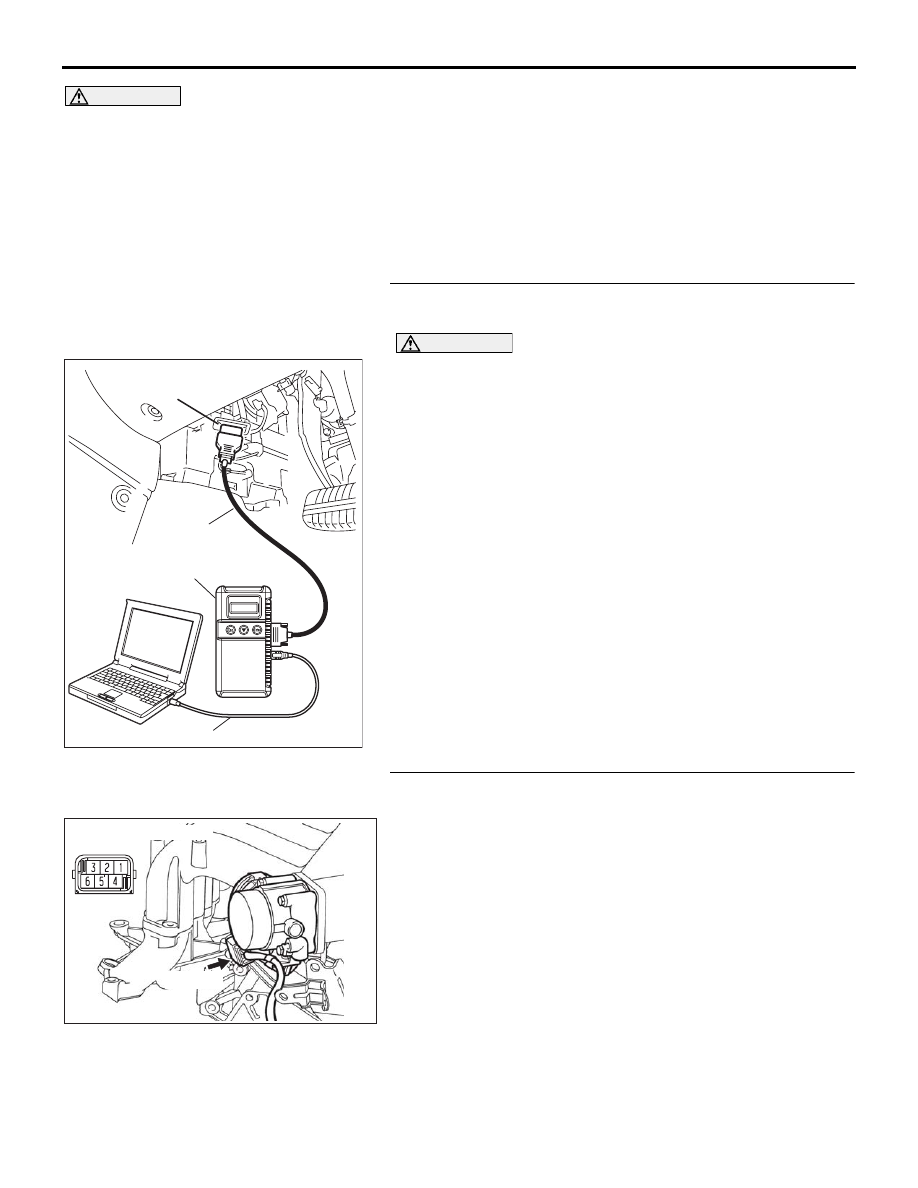
STEP 1. Using diagnostic tool , check data list item 13: 
Throttle Position Sensor (main).

CAUTION

To prevent damage to diagnostic tool , always turn the 
ignition switch to the "LOCK"(OFF) position before con-
necting or disconnecting diagnostic tool .
(1) Connect diagnostic tool to the data link connector.
(2) Turn the ignition switch to the "ON" position.
(3) Set diagnostic tool to the data reading mode for item 13, 

Throttle Position Sensor (main).

(4) Apply the accelerator pedal as required to check the 

following:

• Output voltage should be between 1035 and 1250 mV 

when the throttle valve is fully close.

• Output voltage should be between 4000 and 4824 mV 

when the throttle valve is fully open.

(5) Turn the ignition switch to the "LOCK"(OFF) position.

Q: Is the sensor operating properly?

YES : It can be assumed that this malfunction is intermittent. 

Refer to GROUP 00, How to Use 
Troubleshooting/Inspection Service Points 

− How to 

Cope with Intermittent Malfunctions 

P.00-14

.

NO :  Go to Step 2.

STEP 2. Check harness connector B-06 at throttle position 
sensor for damage.
Q: Is the harness connector in good condition?

YES : Go to Step 3.
NO :  Repair or replace it. Refer to GROUP 00E, Harness 

Connector Inspection 

P.00E-2

. Then go to Step 8.

00DB076A

MB991910

DATA LINK

CONNECTOR

MB991824

MB991827

03DB180A

CONNECTOR: B-06

B-06 (B)

MULTIPORT FUEL INJECTION (MPI) DIAGNOSIS

MULTIPORT FUEL INJECTION (MPI)

13A-157

STEP 3. Check the continuity at throttle position sensor 
harness side connector B-06.
(1) Disconnect the connector B-06 and measure at the harness 

side.

(2) Measure the continuity between terminal No. 2 and ground

• Should be less than 2 ohms.

Q: Does continuity exist?

YES : Go to Step 6.
NO :  Go to Step 4.

STEP 4. Check harness connector B-20 at ENGINE-ECU for 
damage.
Q: Is the harness connector in good condition?

YES : Go to Step 5.
NO :  Repair or replace it. Refer to GROUP 00E, Harness 

Connector Inspection 

P.00E-2

. Then go to Step 7.

03DB180A

CONNECTOR: B-06

B-06 (B)

03DB197A

THROTTLE ACTUATOR

CONTROL MOTOR 

CONNECTOR

16DB400A

COVER

ENGINE

CONTROL

UNIT

AIR

CLEANER

MULTIPORT FUEL INJECTION (MPI) DIAGNOSIS

MULTIPORT FUEL INJECTION (MPI)

13A-158

STEP 5. Check for open circuit and harness damage 
between throttle position sensor connector B-06 (terminal 
No. 2) and ENGINE-ECU connector B-20 (terminal No. 27).
Q: Is the harness wire in good condition?

YES : Go to Step 6.
NO :  Repair or replace it. Then go to Step 7.

STEP 6. Replace the throttle body assembly.
(1) Replace the throttle body assembly.
(2) Turn the ignition switch to the "ON" position.
(3) After the DTC has been deleted, read the DTC again.
(4) Turn the ignition switch to the "LOCK" (OFF) position.

Q: Is DTC P0123 set?

YES : Then go to Step 7. 
NO :  The procedure is complete.

03DB180A

CONNECTOR: B-06

B-06 (B)

16DB400A

COVER

ENGINE

CONTROL

UNIT

AIR

CLEANER

03DB180A

CONNECTOR: B-06

B-06 (B)

MULTIPORT FUEL INJECTION (MPI) DIAGNOSIS

MULTIPORT FUEL INJECTION (MPI)

13A-159

STEP 7. Using diagnostic tool, read the diagnostic trouble 
code (DTC).

CAUTION

To prevent damage to diagnostic tool, always turn the igni-
tion switch to the "LOCK"(OFF) position before connect-
ing or disconnecting diagnostic tool .
(1) Connect diagnostic tool  to the data link connector.
(2) Turn the ignition switch to the "ON" position.
(3) After the DTC has been deleted, read the DTC again.
(4) Turn the ignition switch to the "LOCK"(OFF) position.

Q: Is DTC P0123 set?

YES : Retry the troubleshooting.
NO :  The inspection is complete.

00DB076A

MB991910

DATA LINK

CONNECTOR

MB991824

MB991827


Content   ..  514  515  516  517   ..