Mitsubishi 380. Manual - part 514


  Index      Mitsubishi     Mitsubishi 380 - service repair manual 2005 year


Search            


Content   ..  512  513  514  515   ..


Mitsubishi 380. Manual - part 514


MULTIPORT FUEL INJECTION (MPI) DIAGNOSIS

MULTIPORT FUEL INJECTION (MPI)

13A-148

13A

DTC P0122: Throttle Position Sensor (Main) Circuit Low Input.

CAUTION

If DTC P0122 has been set, TCL related DTC 
U1120 is also set. After P0122 has been diag-
nosed, don't forget to erase DTC U1120.

.

CIRCUIT OPERATION

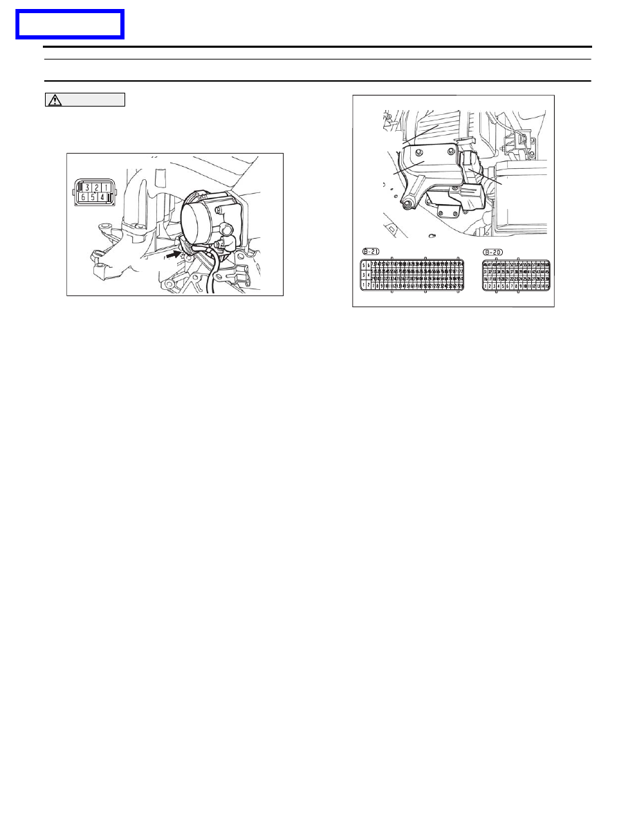
• A 5-volt power supply is applied on the throttle 

position sensor (main) power terminal (terminal 
No. 3) from the ENGINE-ECU connector B-20 
(terminal No. 10).
The ground terminal (terminal No. 2) is grounded 
with ENGINE-ECU connector B-20 (terminal No. 
27).

.

TECHNICAL DESCRIPTION

• The throttle position sensor (main) outputs volt-

age which corresponds to the throttle valve open-
ing angle.

• The ENGINE-ECU checks whether the voltage is 

within a specified range.

.

DTC SET CONDITIONS

Check Condition

• Ignition switch is "ON" position.

Judgement Criteria

• Throttle position sensor (main) output voltage is 

low.

• MIL activated immediately

• Engine speed limited to 1500rpm.

.

EOBD DRIVE CYCLE PATTERN

None.

.

TROUBLESHOOTING HINTS (The most 
likely causes for this code to be set are:)

• Throttle position sensor failed.

• Open or shorted throttle position sensor (main) 

circuit, harness damage, or connector damage.

• Refer to component locations GROUP-

70

• Refer to configuration diagrams GROUP-

80

• Refer to circuit diagrams GROUP-

90

03DB180A

CONNECTOR: B-06

B-06 (B)

16DB400A

COVER

ENGINE

CONTROL

UNIT

AIR

CLEANER

PREVIOUS PAGE

MULTIPORT FUEL INJECTION (MPI) DIAGNOSIS

MULTIPORT FUEL INJECTION (MPI)

13A-149

DIAGNOSIS

Required Special Tools:

•  Diagnostic tool (MUT-III Sub Assembly)

• MB991824: V.C.I.

• MB991827: USB Cable

• MB991910: Main Harness A

• MB991658: Test Harness

WARNING

If the air intake duct is removed from the throttle body take great care to keep fingers away 
from the throttle plate. The drive motor has very high torque and is capable of random move-
ment at any time. Do not under any circumstances activate the throttly plate by hand.
When removing the throttle body from the intake manifold disconnect the wiring first. During 
replacement connect the wiring last.
Do not activate the throttle body using a DC suppy to test the motor,as permanent damage to 
the throttle body will result.

STEP 1. Using diagnostic tool , check data list item 13: 
Throttle Position Sensor (main).

CAUTION

To prevent damage to diagnostic tool , always turn the 
ignition switch to the "LOCK"(OFF) position before con-
necting or disconnecting diagnostic tool .
(1) Connect diagnostic tool to the data link connector.
(2) Turn the ignition switch to the "ON" position.
(3) Set diagnostic tool to the data reading mode for item 13, 

Throttle Position Sensor (main).

(4) Apply the accelerator pedal as required to check the 

following:

• Output voltage should be between 1035 and 1250 mV 

when the throttle valve is fully close.

• Output voltage should be approximately 4000 and 4824 

mV when the throttle valve is fully open.

(5) Turn the ignition switch to the "LOCK"(OFF) position.

Q: Is the sensor operating properly?

YES : It can be assumed that this malfunction is intermittent. 

Refer to GROUP 00, How to Use 
Troubleshooting/Inspection Service Points 

− How to 

Cope with Intermittent Malfunctions 

P.00-14

.

NO :  Go to Step 2.

00DB076A

MB991910

DATA LINK

CONNECTOR

MB991824

MB991827

MULTIPORT FUEL INJECTION (MPI) DIAGNOSIS

MULTIPORT FUEL INJECTION (MPI)

13A-150

STEP 2. Check harness connector B-06 at throttle position 
sensor for damage.
Q: Is the harness connector in good condition?

YES : Go to Step 3.
NO :  Repair or replace it. Refer to GROUP 00E, Harness 

Connector Inspection 

P.00E-2

. Then go to Step 9.

STEP 3. Measure the sensor supply voltage at throttle 
position sensor harness side connector B-06.
(1) Disconnect the connector B-06 and measure at the harness 

side.

(2) Turn the ignition switch to the "ON" position.

(3) Measure the voltage between terminal No. 3 and ground.

• Voltage should be between 4.9 and 5.1 volts.

(4) Turn the ignition switch to the "LOCK"(OFF) position.

Q:  Is the measured voltage between 4.9 and 5.1 volts?

YES : Go to Step 6.
NO :  Go to Step 4.

03DB180A

CONNECTOR: B-06

B-06 (B)

03DB180A

CONNECTOR: B-06

B-06 (B)

03DB195A

THROTTLE ACTUATOR

CONTROL MOTOR 

CONNECTOR

MULTIPORT FUEL INJECTION (MPI) DIAGNOSIS

MULTIPORT FUEL INJECTION (MPI)

13A-151

STEP 4. Check harness connector B-20 at ENGINE-ECU for 
damage.
Q: Is the harness connector in good condition?

YES : Go to Step 5.
NO :  Repair or replace it. Refer to GROUP 00E, Harness 

Connector Inspection 

P.00E-2

. Then go to Step 9.

STEP 5. Check for open circuit and short circuit to ground 
between throttle position sensor connector B-06 (terminal 
No. 3) and ENGINE-ECU connector B-20 (terminal No. 10).
Q: Is the harness wire in good condition?

YES : Go to Step 6.
NO :  Repair or replace it. Then go to Step 9.

16DB400A

COVER

ENGINE

CONTROL

UNIT

AIR

CLEANER

03DB180A

CONNECTOR: B-06

B-06 (B)

16DB400A

COVER

ENGINE

CONTROL

UNIT

AIR

CLEANER


Content   ..  512  513  514  515   ..