Mitsubishi 380. Manual - part 500


  Index      Mitsubishi     Mitsubishi 380 - service repair manual 2005 year


Search            


Content   ..  498  499  500  501   ..


Mitsubishi 380. Manual - part 500


MULTIPOINT FUEL INJECTION (MPI) DIAGNOSIS

MULTIPOINT FUEL INJECTION (MPI)

13A-92

DTC P0106: Manifold Absolute Pressure Circuit Range/Performance Problem.

.

CIRCUIT OPERATION

• A 5-volt voltage is supplied to the manifold abso-

lute pressure sensor power terminal (terminal No. 
3) from the ENGINE-ECU (terminal No. 25). The 
ground terminal (terminal No. 2) is grounded with 
ENGINE-ECU (terminal No. 12).

• A voltage that is proportional to the intake mani-

fold pressure is sent to the ENGINE-ECU (termi-
nal No. 41) from the manifold absolute pressure 
sensor output terminal (terminal No. 1).

.

TECHNICAL DESCRIPTION

• The manifold absolute pressure sensor outputs a 

voltage which corresponds to the intake manifold 
pressure.

• The ENGINE-ECU checks whether this voltage is 

within a specified range.

.

DTC SET CONDITIONS <Range/Performance problem>

Check Conditions

• None

Judgement Criteria

• MAP sensor output is above upper threshold 

(223 - 1300 hPa) for 2 seconds.
or
MAP sensor output is below lower threshold (0 - 
395 kg/h) for 2 seconds.

• MIL is activated after 2 Drive cycles.

• No limp home mode (backed-up by AFS).

.

EOBD DRIVE CYCLE PATTERN

Refer to Diagnostic Function 

− EOBD Drive Cycle − 

P.13A-11

.

.

TROUBLESHOOTING HINTS (The most 
likely causes for this code to be set are: )

• Manifold absolute pressure sensor failed.

• Harness damage.

• Connector damage.

• Refer to component locations GROUP-

70

• Refer to configuration diagrams GROUP-

80

• Refer to circuit diagrams GROUP-
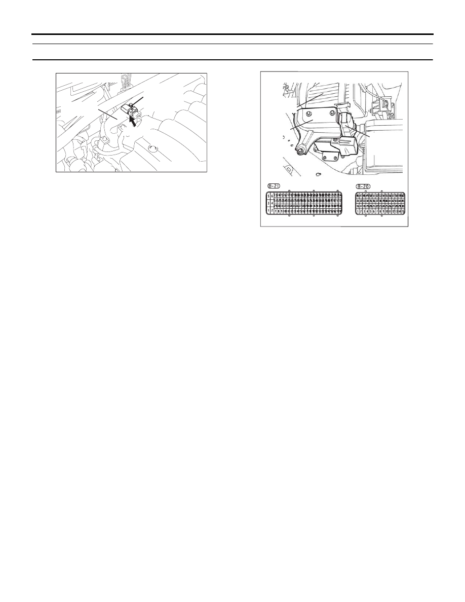
90

03DB222A

CONNECTOR: B-02

MANIFOLD

ABSOLUTE

PRESSURE

SENSOR

INTAKE

MANIFOLD

B-02 (B)

16DB400A

COVER

ENGINE

CONTROL

UNIT

AIR

CLEANER

MULTIPOINT FUEL INJECTION (MPI) DIAGNOSIS

MULTIPOINT FUEL INJECTION (MPI)

13A-93

DIAGNOSIS

Required Special Tools:

• : Diagnostic Tool (MUT-III Sub Assembly)

• MB991824: V.C.I.

• MB991827: USB Cable

• MB991910: Main Harness A

• MB992044:  ECU Check Harness

STEP 1. Measure the sensor output voltage at 
ENGINE-ECU connector B-20 by using  ECU check 
harness special tool MB992044.
(1) Disconnect the all ENGINE-ECU connectors and connect  

ECU check harness special tool MB992044 between the 
separated connectors.

(2) Turn the ignition switch to the "ON" position.

(3) Measure the voltage between terminal No. 41 of 

ENGINE-ECU check harness and ground.

• When altitude is 0 m, voltage should be 4.01 to 4.15 

volts.

• When altitude is 600 m, voltage should be 3.76 to 3.92 

volts.

• When altitude is 1,200 m, voltage should be 3.45 to 3.62 

volts.

• When altitude is 1,800 m, voltage should be 3.2 to 3.3 

volts.

(4) Turn the ignition switch to the "LOCK" (OFF) position.

Q: Is the measured voltage correct?

YES : It can be assumed that this malfunction is intermittent. 

Refer to GROUP 00, How to Use 
Troubleshooting/Inspection Service Points 

− How to 

Cope with Intermittent Malfunctions 

P.00-14

.

NO :  Go to Step 2.

16DB400A

COVER

ENGINE

CONTROL

UNIT

AIR

CLEANER

03DB224A

B-20 HARNESS 

CONNECTOR 

MULTIPOINT FUEL INJECTION (MPI) DIAGNOSIS

MULTIPOINT FUEL INJECTION (MPI)

13A-94

STEP 2. Measure the sensor supply voltage at 
ENGINE-ECU connector B-20 by using  ECU check 
harness special tool MB992044.
(1) Disconnect the all ENGINE-ECU connectors and connect  

ECU check harness special tool MB992044 between the 
separated connectors.

(2) Turn the ignition switch to the "ON" position.

(3) Measure the sensor supply voltage between terminal No. 

25 and ground.

• Voltage should be between 4.9 and 5.1 volts.

(4) Turn the ignition switch to the "LOCK" (OFF) position.

Q: Is the measured voltage between 4.9 and 5.1 volts?

YES : Go to Step 3.
NO :  Repair or replace it. Refer to GROUP 00E, Harness 

Connector Inspection 

P.00E-2

. Then go to Step 10.

1

2

3

CONNECTOR: B-02

03DB223A

MANIFOLD

ABSOLUTE

PRESSURE

SENSOR

INTAKE

MANIFOLD

B-02 (B)

HARNESS 

CONNECTOR:

COMPONENT SIDE

03DB225A

B-20 HARNESS 

CONNECTOR 

MULTIPOINT FUEL INJECTION (MPI) DIAGNOSIS

MULTIPOINT FUEL INJECTION (MPI)

13A-95

STEP 3. Check harness connector B-02 at the manifold 
absolute pressure sensor and harness connector B-20 at 
ENGINE-ECU for damage.
Q: Is the harness connector in good condition?

YES : Go to step 4.
NO :  Repair or replace it. Refer to GROUP 00E, Harness 

Connector Inspection 

P.00E-2

. Then go to Step 10.

1

2

3

CONNECTOR: B-02

03DB223A

MANIFOLD

ABSOLUTE

PRESSURE

SENSOR

INTAKE

MANIFOLD

B-02 (B)

HARNESS 

CONNECTOR:

COMPONENT SIDE

16DB400A

COVER

ENGINE

CONTROL

UNIT

AIR

CLEANER


Content   ..  498  499  500  501   ..