Mitsubishi 380. Manual - part 499
MULTIPOINT FUEL INJECTION (MPI) DIAGNOSIS
MULTIPOINT FUEL INJECTION (MPI)
13A-88
DIAGNOSIS
Required Special Tool:
• : Diagnostic Tool (MUT-III Sub Assembly)
• MB991824: V.C.I.
• MB991827: USB Cable
• MB991910: Main Harness A
STEP 1. Using diagnostic tool , check data list item AA:
Mass Airflow Sensor.
CAUTION
To prevent damage to diagnostic tool , always turn the
ignition switch to the "LOCK" (OFF) position before con-
necting or disconnecting diagnostic tool .
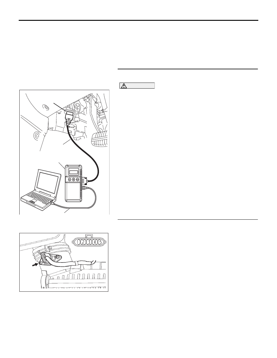
(1) Connect diagnostic tool to the data link connector.
(2) Start the engine and run at idle.
(3) Set diagnostic tool to the data reading mode for item AA,
Mass Airflow Sensor.
(4) Warm up the engine to normal operating temperature: 80
°C
to 95
°C (176°F to 203°F).
• The standard value during idling should be approxi-
mately 4.7 g/sec.
• When the engine is revved, the mass airflow rate should
increase according to the increase in engine speed.
(5) Turn the ignition switch to the "LOCK" (OFF) position.
Q: Is the sensor operating properly?
YES : It can be assumed that this malfunction is intermittent.
Refer to GROUP 00, How to Use
Troubleshooting/Inspection Service Points
− How to
Cope with Intermittent Malfunctions
.
NO : Go to Step 2.
STEP 2. Check harness connector B-10 at mass airflow
sensor for damage.
Q: Is the harness connector in good condition?
YES : Go to Step 3.
NO : Repair or replace it. Refer to GROUP 00E, Harness
Connector Inspection
. Then go to Step 7.
00DB076A
MB991910
DATA LINK
CONNECTOR
MB991824
MB991827
CONNECTOR: B-10
B-10 (GR)
03DB218A
HARNESS
CONNECTOR:
COMPONENT SIDE