Mitsubishi 380. Manual - part 495


  Index      Mitsubishi     Mitsubishi 380 - service repair manual 2005 year


Search            


Content   ..  493  494  495  496   ..


Mitsubishi 380. Manual - part 495


MULTIPOINT FUEL INJECTION (MPI) DIAGNOSIS

MULTIPOINT FUEL INJECTION (MPI)

13A-72

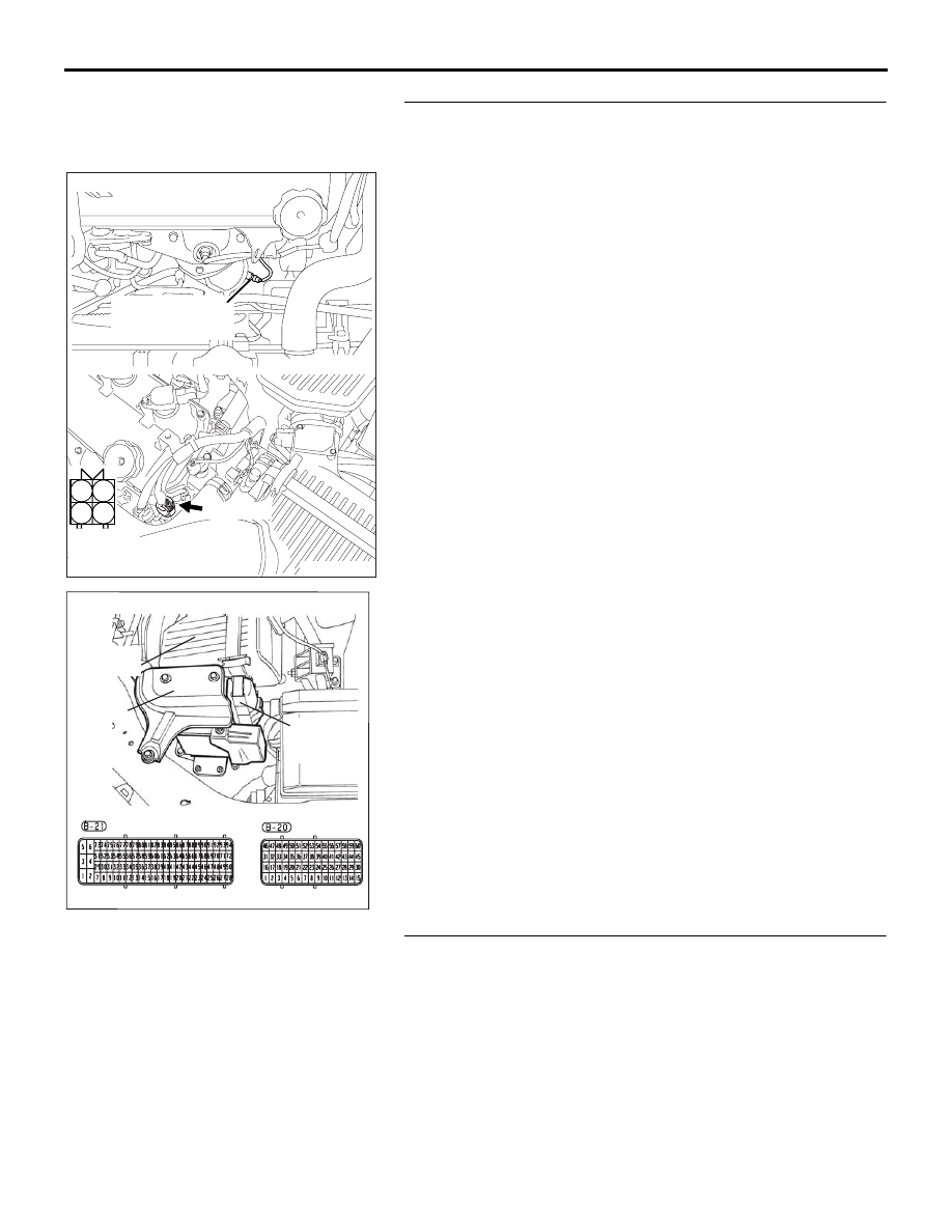
STEP 10. Check for harness damage between left bank 
heated oxygen sensor (rear) connector B-24 (terminal No. 
3) and ENGINE-ECU connector B-20 (terminal No. 33).
Q: Is the harness wire in good condition?

YES : Go to Step 11.
NO :  Repair it. Then go to Step 11.

STEP 11. Test the EOBD drive cycle.
(1) Carry out a test drive with the drive cycle pattern. Refer to 

Diagnostic Function 

− EOBD Drive Cycle − 

P.13A-11

.

(2) Check the diagnostic trouble code (DTC).

Q: Is DTC P0057 set?

YES : Retry the troubleshooting.
NO :  The inspection is complete.

16DB400A

COVER

ENGINE

CONTROL

UNIT

AIR

CLEANER

1

2

3

4

AK303079

HARNESS

CONNECTOR:

COMPONENT SIDE

CONNECTOR: B-24

AB

LEFT BANK

HEATED OXYGEN

SENSOR (REAR)

B-24 (GR)

MULTIPOINT FUEL INJECTION (MPI) DIAGNOSIS

MULTIPOINT FUEL INJECTION (MPI)

13A-73

DTC P0058: Heated Oxygen Sensor Heater Circuit high (bank 2, sensor 2).

.

CIRCUIT OPERATION

• Power is supplied from the MPI relay (terminal 

No. 4) to the left bank heated oxygen sensor 
(rear) heater.

• The ENGINE-ECU (terminal No. 33) controls 

continuity to the left bank heated oxygen sensor 
(rear) heater by turning the power transistor in the 
ENGINE-ECU "ON" and "OFF".

.

TECHNICAL DESCRIPTION

• The ENGINE-ECU checks whether the heater 

current is within a specified range when the 
heater is energized.

.

DTC SET CONDITIONS

Check Conditions

• Battery voltage is within 9.04 to 16.01 volts.

• Engine speed is above 801 r/min.

Judgment Criteria

• IC internal test (short circuit to battery)

• MIL is activated after 2 Driving Cycles.

• No limp home mode.

1

2

3

4

1

2

3

4

1

2

3

4

1

2

3

4

AK303014

CONNECTOR: B-17X

MFI RELAY

MFI RELAY

FRONT OF VEHICLE

B-17X

AB

16DB400A

COVER

ENGINE

CONTROL

UNIT

AIR

CLEANER

1

2

3

4

AK303079

HARNESS

CONNECTOR:

COMPONENT SIDE

CONNECTOR: B-24

AB

LEFT BANK

HEATED OXYGEN

SENSOR (REAR)

B-24 (GR)

MULTIPOINT FUEL INJECTION (MPI) DIAGNOSIS

MULTIPOINT FUEL INJECTION (MPI)

13A-74

.

EOBD DRIVE CYCLE PATTERN

Refer to Diagnostic Function 

− EOBD Drive Cycle − 

P.13A-11

.

.

TROUBLESHOOTING HINTS (The most 
likely causes for this code to be set are: )

• Open or shorted left bank heated oxygen sensor 

(rear) heater circuit, harness damage, or connec-
tor damage.

• Left bank heated oxygen sensor (rear) heater 

failed.

• Short circuit to 12 Volts.

• Connector damaged.

• Refer to component locations GROUP-

70

• Refer to configuration diagrams GROUP-

80

• Refer to circuit diagrams GROUP-

90

DIAGNOSIS

Required Special Tools:

•  Diagnostic tool (MUT-III Sub Assembly)

• MB991824: V.C.I.

• MB991827: USB Cable

• MB991910: Main Harness A

• MB992044:  ENGINE-ECU Check Harness

STEP 1. Check harness connector B-09 at the left bank 
heated oxygen sensor (rear) for damage.
Q: Is the harness connector in good condition?

YES : Go to Step 2.
NO :  Repair or replace it. Refer to GROUP 00E, Harness 

Connector Inspection 

P.00E-2

. Then go to Step 4.

1

2

3

4

AK303048

B-09 (B)

CONNECTOR: B-09

THROTTLE BODY

RIGHT BANK

HEATED OXYGEN

SENSOR (FRONT)

AB

HARNESS

CONNECTOR:

COMPONENT SIDE

MULTIPOINT FUEL INJECTION (MPI) DIAGNOSIS

MULTIPOINT FUEL INJECTION (MPI)

13A-75

STEP 2. Check the left bank heated oxygen sensor (rear).
(1) Disconnect left bank heated oxygen sensor (rear) connector 

B-24.

(2) Measure the resistance between heated oxygen sensor 

connector terminal No. 3 and terminal No. 4.

Standard value: 9.0 

 11.0 ohms [at 20°C (68°F)]

Q: Is the measured resistance between 9.0 and 11.0 ohms 

[at 20

°C (68°F)]?

YES : Go to Step 3.
NO :  Replace the left bank heated oxygen sensor (rear). 

Then go to Step 4.

STEP 3. Check the trouble symptoms.
(1) Carry out a test drive with the drive cycle pattern. Refer to 

Diagnostic Function 

− EOBD Drive Cycle − 

P.13A-11

.

(2) Check the diagnostic trouble code (DTC).

Q: Is DTC P0058 set?

YES : Then go to Step 4.
NO :  It can be assumed that this malfunction is intermittent. 

Refer to GROUP 00, How to Use 
Troubleshooting/Inspection Service Points 

− How to 

Cope with Intermittent Malfunctions 

P.00-14

STEP 4. Test the EOBD drive cycle.
(1) Carry out a test drive with the drive cycle pattern. Refer to 

Diagnostic Function 

− EOBD Drive Cycle − 

P.13A-11

.

(2) Check the diagnostic trouble code (DTC).

Q: Is DTC P0058 set?

YES : Retry the troubleshooting.
NO :  The inspection is complete.

AK303071

1

2

3

4

LEFT BANK

HEATED OXYGEN

SENSOR (FRONT)

CONNECTOR: B-25

B-25 (B)

AB

HARNESS

CONNECTOR:

COMPONENT SIDE


Content   ..  493  494  495  496   ..