Mitsubishi 380. Manual - part 493


  Index      Mitsubishi     Mitsubishi 380 - service repair manual 2005 year


Search            


Content   ..  491  492  493  494   ..


Mitsubishi 380. Manual - part 493


MULTIPOINT FUEL INJECTION (MPI) DIAGNOSIS

MULTIPOINT FUEL INJECTION (MPI)

13A-64

• The heater voltage is less than 2.4 V during the 

calibrated time interval.
or

• The heater voltage is not within 2.4 - 3.6 Volts 

during the calibrated time interval.

• MIL is activated after 2 Driving Cycles.

• No limp home mode.

.

EOBD DRIVE CYCLE PATTERN

Refer to Diagnostic Function 

− EOBD Drive Cycle − 

P.13A-11

.

.

TROUBLESHOOTING HINTS (The most 
likely causes for this code to be set are: )

• Open or shorted left bank heated oxygen sensor 

(rear) heater circuit, harness damage, or connec-
tor damage.

• Left bank heated oxygen sensor (rear) heater 

failed.

• Refer to component locations GROUP-

70

• Refer to configuration diagrams GROUP-

80

• Refer to circuit diagrams GROUP-

90

DIAGNOSIS

Required Special Tools:

•  Diagnostic tool (MUT-III Sub Assembly)

• MB991824: V.C.I.

• MB991827: USB Cable

• MB991910: Main Harness A

• MB992044:  ENGINE-ECU Check Harness

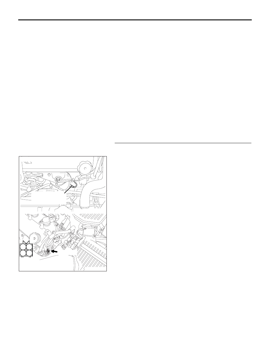
STEP 1. Check harness connector B-24 at the left bank 
heated oxygen sensor (rear) for damage.
Q: Is the harness connector in good condition?

YES : Go to Step 2.
NO :  Repair or replace it. Refer to GROUP 00E, Harness 

Connector Inspection 

P.00E-2

. Then go to Step 11.

1

2

3

4

AK303079

HARNESS

CONNECTOR:

COMPONENT SIDE

CONNECTOR: B-24

AB

LEFT BANK

HEATED OXYGEN

SENSOR (REAR)

B-24 (GR)

MULTIPOINT FUEL INJECTION (MPI) DIAGNOSIS

MULTIPOINT FUEL INJECTION (MPI)

13A-65

STEP 2. Check the left bank heated oxygen sensor (rear).
(1) Disconnect left bank heated oxygen sensor (rear) connector 

B-24.

(2) Measure the resistance between heated oxygen sensor 

connector terminal No. 3 and terminal No. 4.

Standard value: 9.0 

 11.0 ohms [at 20°C (68°F)]

Q: Is the measured resistance between 9.0 and 11.0 ohms 

[at 20

°C (68°F)]?

YES : Go to Step 3.
NO :  Replace the left bank heated oxygen sensor (rear). 

Then go to Step 11.

1

2

3

4

AK303079

HARNESS

CONNECTOR:

COMPONENT SIDE

CONNECTOR: B-24

AB

LEFT BANK

HEATED OXYGEN

SENSOR (REAR)

B-24 (GR)

MULTIPOINT FUEL INJECTION (MPI) DIAGNOSIS

MULTIPOINT FUEL INJECTION (MPI)

13A-66

STEP 3. Measure the power supply voltage at left bank 
heated oxygen sensor (rear) harness side connector B-24.
(1) Disconnect the connector B-24 and measure at the harness 

side.

(2) Turn the ignition switch to the "ON" position.

(3) Measure the voltage between terminal No. 4 and ground.

• Voltage should be battery positive voltage.

(4) Turn the ignition switch to the "LOCK" (OFF) position.

Q: Is battery positive voltage (approximately 12 volts) 

present?
YES : 
Go to Step 5.
NO :  Go to Step 4.

1

2

3

4

AK303079

HARNESS

CONNECTOR:

COMPONENT SIDE

CONNECTOR: B-24

AB

LEFT BANK

HEATED OXYGEN

SENSOR (REAR)

B-24 (GR)

03DB229A

B-25 HARNESS 

CONNECTOR: 

COMPONENT SIDE

1

2

3

4

MULTIPOINT FUEL INJECTION (MPI) DIAGNOSIS

MULTIPOINT FUEL INJECTION (MPI)

13A-67

STEP 4. Check harness connector B-17X at the MPI relay 
for damage.
Q: Is the harness connector in good condition?

YES : Repair harness wire between MPI relay connector 

B-17X (terminal No. 4) and left bank heated oxygen 
sensor (rear) connector B-24 (terminal No. 4) 
because of open circuit or short circuit to ground. 
Then go to Step 11.

NO :  Repair or replace it. Refer to GROUP 00E, Harness 

Connector Inspection 

P.00E-2

. Then go to Step 11. 

1

2

3

4

AK303017

CONNECTOR: B-17X

FRONT OF VEHICLE

B-17X

AB

HARNESS

CONNECTOR:

COMPONENT SIDE

RELAY BOX


Content   ..  491  492  493  494   ..