Mitsubishi 380. Manual - part 478


  Index      Mitsubishi     Mitsubishi 380 - service repair manual 2005 year


Search            


Content   ..  476  477  478  479   ..


Mitsubishi 380. Manual - part 478


GENERAL DESCRIPTION

MULTIPOINT FUEL INJECTION (MPI)

13A-4

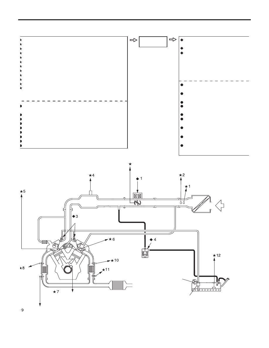
MULTIPOINT FUEL INJECTION (MPI) SYSTEM DIAGRAM

NOTE: For the vacuum routing, refer to GROUP 17, Emission Control System 

 Vacuum Hoses  Vacuum 

Hose Routing 

P.17-77

.

MANIFOLD

ABSOLUTE

PRESSURE

SENSOR

THROTTLE

ACTUATOR

CONTROL

MOTOR

CAMSHAFT

POSITION

SENSOR

LEFT BANK HEATED OXYGEN

SENSOR (FRONT)

FUEL TANK

    3 THROTTLE POSITION SENSOR

       (MAIN/SUB)

MASS AIRFLOW

SENSOR

ENGINE

COOLANT

TEMPERATURE

SENSOR

GHT BANK

ATED

YGEN

NSOR

RONT)

RIGHT BANK HEATED

OXYGEN SENSOR (REAR)

FUEL PRESSURE

REGULATOR

LEFT BANK HEATED OXYGEN

SENSOR (REAR)

FUEL PUMP

CRANKSHAFT POSITION

SENSOR

FUEL

LEVEL

SENSOR

AIR

INLET

INTAKE AIR TEMPERATURE

SENSOR

EVAPORATIVE

EMISSION

PURGE SOLENOID

INJECTOR

1   MASS AIRFLOW SENSOR

2   INTAKE AIR TEMPERATURE SENSOR

3   THROTTLE POSITION SENSOR (MAIN/SUB)

4   MANIFOLD ABSOLUTE PRESSURE SENSOR

5   ENGINE COOLANT TEMPERATURE SENSOR

6   CAMSHAFT POSITION SENSOR

7   CRANKSHAFT POSITION SENSOR

8   RIGHT BANK HEATED OXYGEN SENSOR (FRONT)

9   RIGHT BANK HEATED OXYGEN SENSOR (REAR)

10 LEFT BANK HEATED OXYGEN SENSOR (FRONT)  

11 LEFT BANK HEATED OXYGEN SENSOR (REAR)

12 FUEL LEVEL SENSOR


     ACCELERATOR PEDAL POSITION SENSOR 

     (MAIN/SUB)

     KNOCK SENSOR

     POWER STEERING PRESSURE SWITCH

     OUTPUT SHAFT SPEED SENSOR

     TRANSMISSION RANGE SWITCH

     IGNITION SWITCH-IG

     IGNITION SWITCH-ST

     POWER SUPPLY     

1   THROTTLE ACTUATOR

     CONTROL MOTOR

2   INJECTOR

3   EVAPORATIVE EMISSION 

     PURGE SOLENOID


     IGNITION COIL, IGNITION

     POWER TRANSISTER

     MULTIPOINT FUEL 

     INJECTION (MPI) RELAY

     FUEL PUMP RELAY

     THROTTLE ACTUATOR 

     CONTROL MOTOR RELAY

     ALTERNATOR G TERMINAL

     HEATED OXYGEN SENSOR

     HEATER

     FAN CONTROL MODULE

     (RADIATOR, A/C CONDENSER)

     A/C COMPRESSOR CLUTCH 

     RELAY

     DIAGNOSTIC OUTPUT

ENGINE-ECU

ENSE

DECIDE

ACT

MULTIPOINT FUEL INJECTION (MPI) DIAGNOSIS

MULTIPOINT FUEL INJECTION (MPI)

13A-5

MULTIPOINT FUEL INJECTION (MPI) DIAGNOSIS

TROUBLESHOOTING STRATEGY

M1131150001204

Use these steps to plan your diagnostic strategy. If 
you follow them carefully, you will be sure to have 
exhausted most of the possible ways to find an MPI 
fault.
1. Gather as much information as possible about the 

complaint from the customer.

2. Verify that the condition described by the 

customer exists.

3. Check the vehicle for any MPI Diagnostic Trouble 

Code (DTC).

4. If you cannot verify the condition and there are no 

DTCs, the malfunction is intermittent. For 
information on how to cope with intermittent 
malfunctions, refer to GROUP 00, How to Use 
Troubleshooting/Inspection Service Points 

− How 

to Cope with Intermittent Malfunction

P.00-14

.

5. If you can verify the condition but there are no 

DTCs, or the system cannot communicate with 
the diagnostic tool, refer to the trouble symptom 
classification table.

6. If there is a DTC, record the number of the code, 

then erase the code from the memory using the 
diagnostic tool.

7. Reconfirm the malfunction symptom and carry out 

a test drive with the appropriate drive cycle 
pattern.

8. If DTC is set again, carry out an inspection with 

appropriate diagnostic trouble code procedures. 
Refer to Diagnostic Trouble Code Chart 

P.13A-17

9. If DTC is not set again, the malfunction is 

intermittent. For information on how to cope with 
intermittent malfunctions, refer to GROUP 00, 
How to Use Troubleshooting/Inspection Service 
Points 

− How to Cope with Intermittent 

Malfunctions 

P.00-14

.

10.After repairs are completed, conduct a road test 

duplicating the complaint set conditions to confirm 
the malfunction has been corrected.

NOTE:  If the ENGINE-ECU is replaced, Immobilizer 
Encrypted Code Registration should be carried out, 
Refer to GROUP 54A, Ignition Switch 

 On-vehicle 

Service 

 Immobilizer Encrypted Code Registration 

P.54A-37

.

DIAGNOSTIC FUNCTION

M1131155500881

.

CHECK ENGINE WARNING LAMP

Among the on-board diagnostic items, Check Engine Warning 
Lamp illuminates to notify the driver of an emission control or 
major engine operating systemmalfunction. 
However, when an irregular signal returns to normal and the 
Engine-ECU judges that it has returned to normal, the Check 
Engine Warning Lamp is switched off. 
Immediately after the ignition switch is turned on, the Check 
Engine Warning Lamp) is lit for 20 seconds to indicate that the  
Check Engine Warning Lamp) operates normally. 

MALFUNCTION  INDICATOR

LAMP (SERVICE  ENGINE  SOON 

             or Check Engine Lamp)

03DB216A

MULTIPOINT FUEL INJECTION (MPI) DIAGNOSIS

MULTIPOINT FUEL INJECTION (MPI)

13A-6

HOW TO CONNECT THE DIAGNOSTIC TOOL 
(MUT-III)

Required Special Tools:

• : Diagnostic Tool (MUT-III Sub Assembly)

• MB991824: V.C.I

• MB991827: USB Cable

• MB991910: Main Harness A

CAUTION

To prevent damage to diagnostic tool , always turn the 
ignition switch to the "LOCK" (OFF) position before con-
necting or disconnecting diagnostic tool .
1. Ensure that the ignition switch is at the "LOCK" (OFF) 

position.

2. Start up the personal computer.

3. Connect special tool MB991827 to special tool MB991824 

and the personal computer.

4. Connect special tool MB991910 to special tool MB991824.

5. Connect special tool MB991910 to the data link connector.

6. Turn the power switch of special tool MB991824 to the "ON" 

position.

NOTE: When the special tool MB991824 is energised, spe-
cial tool MB991824 indicator lamp will be illuminated in a 
green color.

7. Start the MUT-III system on the personal computer.

8. Select "System select."

9. Ensure Model & Class details are correctly entered. Refer to 

MUTT III Operaters Manual if in doubt.

NOTE: Disconnecting the diagnostic tool  is the reverse of 
the connecting sequence, making sure that the ignition 
switch is at the "LOCK" (OFF) position.

HOW TO READ AND ERASE DIAGNOSTIC 
TROUBLE CODES.

Required Special Tools:

• : Diagnostic Tool (MUT-III Sub Assembly)

• MB991824: V.C.I.

• MB991827: USB Cable

• MB991910: Main Harness A

CAUTION

To prevent damage to diagnostic tool , always turn the 
ignition switch to the "LOCK" (OFF) position before con-
necting or disconnecting diagnostic tool .

NOTE: If the battery voltage is low, diagnostic trouble codes will 
not be set. Check the battery if diagnostic tool  does not dis-
play.

00DB076A

MB991910

DATA LINK

CONNECTOR

MB991824

MB991827

MULTIPOINT FUEL INJECTION (MPI) DIAGNOSIS

MULTIPOINT FUEL INJECTION (MPI)

13A-7

1. Connect diagnostic tool  to the data link connector.

2. Turn the ignition switch to the "ON" position.

3. Select "System select."

4. Ensure Model & Class details are correctly entered. Refer to 

MUTT III Operaters Manual if in doubt.

5. Choose "MPI" from the System List.

6. Select "Self Diagnosis" tab.

7. If a DTC is set, it is shown.

8. Choose "Erase DTCs" to erase the DTC.

HOW TO READ DATA LIST

Required Special Tools:

• : Diagnostic Tool (MUT-III Sub Assembly)

• MB991824: V.C.I.

• MB991827: USB Cable

• MB991910: Main Harness A

CAUTION

To prevent damage to diagnostic tool , always turn the 
ignition switch to the "LOCK" (OFF) position before con-
necting or disconnecting diagnostic tool .
1. Connect diagnostic tool  to the data link connector.

2. Turn the ignition switch to the "ON" position.

3. Select "System select."

4. Choose "MPI" from the System List.

5. Select "Data List."

6. Choose an appropriate item and select the "OK" button(tick).

00DB076A

MB991910

DATA LINK

CONNECTOR

MB991824

MB991827

00DB076A

MB991910

DATA LINK

CONNECTOR

MB991824

MB991827


Content   ..  476  477  478  479   ..