Mitsubishi 380. Manual - part 423
AUTOMATIC TRANSMISSION DIAGNOSIS
AUTOMATIC TRANSMISSION
23A-232
INSPECTION PROCEDURE 7: Shift Shock when Shifting from "N" to "R" and Long Delay
.
COMMENT
If abnormal shock or delay of two seconds or more
occurs when the selector lever is shifted from "N" to
"R" range while the engine is idling, the cause is
probably abnormal reverse clutch pressure or
low-reverse brake pressure, or a malfunction of the
reverse clutch, low-reverse brake, valve body or TP
sensor.
.
TROUBLESHOOTING HINTS (The most
likely causes for this condition:)
• Abnormal reverse clutch pressure
• Abnormal low-reverse brake pressure
• Malfunction of the low-reverse solenoid valve
• Malfunction of the reverse clutch
• Malfunction of the low-reverse brake
• Malfunction of the valve body
• Malfunction of the TP sensor
• Malfunction of the A/T-ECU system
Circuit drawings
• Refer to circuit diagrams GROUP-
• Refer to configuration diagrams GROUP-
• Refer to component locations GROUP-
DIAGNOSIS
Required Special Tool:
• MB991958: Diagnostic Tool (MUT-III Sub Assembly)
• MB991824: V.C.I.
• MB991827: MUT-III USB Cable
• MB991910: MUT-III Main Harness A
STEP 1. Using diagnostic tool MB991958, check actuator
test item 01: Low-Reverse Solenoid Valve.
CAUTION
To prevent damage to diagnostic tool MB991958, always
turn the ignition switch to the "LOCK" (OFF) position
before connecting or disconnecting diagnostic tool
MB991958.
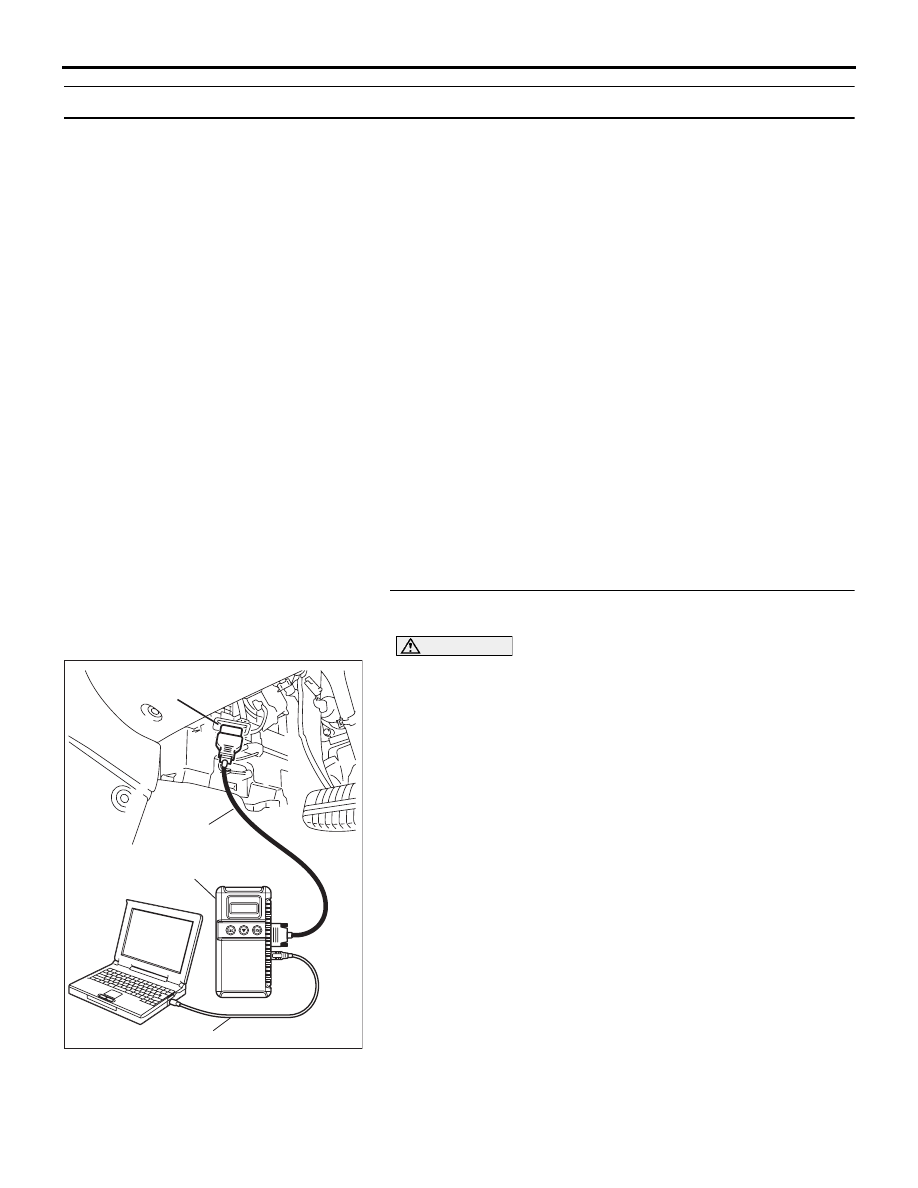
(1) Connect diagnostic tool MB991958 to the data link
connector.
(2) Turn the ignition switch to the "ON" position.
(3) Set diagnostic tool MB991958 to the actuator test mode.
• Item 01: Low-Reverse Solenoid Valve.
• An audible clicking or buzzing should be heard when
the low-reverse solenoid valve is energized.
(4) Turn the ignition switch to the "LOCK" (OFF) position.
Q: Is the solenoid valve operating properly?
YES : Go to Step 2.
NO : Repair or replace the low-reverse solenoid valve.
Refer to GROUP 23B, Valve Body
. Then
confirm that the symptom is eliminated.
00DB076A
MB991910
DATA LINK
CONNECTOR
MB991824
MB991827