Mitsubishi 380. Manual - part 421


  Index      Mitsubishi     Mitsubishi 380 - service repair manual 2005 year


Search            


Content   ..  419  420  421  422   ..


Mitsubishi 380. Manual - part 421


AUTOMATIC TRANSMISSION DIAGNOSIS

AUTOMATIC TRANSMISSION

23A-224

STEP 2. Check the hydraulic pressure (for reverse clutch).
Measure the hydraulic pressure for the reverse clutch when the 
selector lever is at the "R" range, and check if the hydraulic 
pressure is within the standard value. Refer to 

P.23A-26

Hydraulic Pressure Test.

Q: Is the hydraulic pressure within the standard value?

YES : Go to Step 3.
NO :  Go to Step 5.

STEP 3. Check the hydraulic pressure (for low-reverse 
brake).
Measure the hydraulic pressure for the low-reverse brake when 
the selector lever is at the "R" range, and check if the hydraulic 
pressure is within the standard value. Refer to 

P.23A-26

Hydraulic Pressure Test.

Q: Is the hydraulic pressure within the standard value?

YES : Go to Step 4.
NO :  Go to Step 5.

STEP 4. Check the reverse clutch system and low-reverse 
brake system.
(1) Remove the valve body cover and valve body. Refer to  

P.23A-304

 <F5A5A>, Transmission Assembly and GROUP 

23B, Transmission 

P.23B-13

.

(2) Blow 108 kPa (15psi) compressed air into the reverse 

clutch oil orifice of the transmission case. Then check if the 
reverse clutch piston moves and air pressures are 
maintained in that condition. Repeat for the low-reverse 
brake.

Q: Are the reverse clutch, low-reverse brake or both air 

pressures maintained?
YES : 
Go to Step 5.
NO :  Go to Step 6.

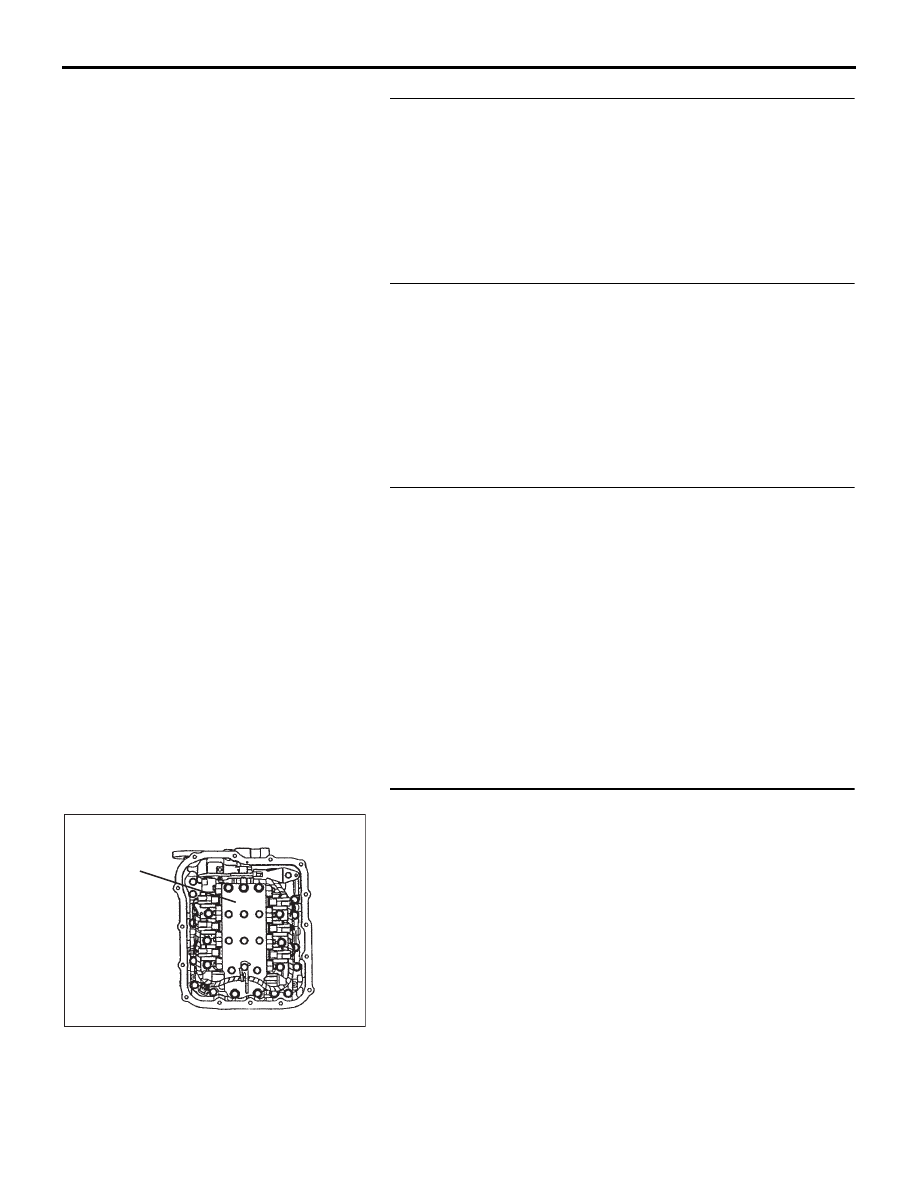
STEP 5. Disassemble and clean the valve body.
Check the O-ring installation bolts for looseness and valve 
body for damage. Repair or replace the faulty parts. Refer to 
GROUP 23B, Valve Body 

P.23B-62

.

Replace the valve body assembly if the damages are thought 
to be irreparable. Then check the symptom.

Q: Is the symptom eliminated?

YES : The procedure is complete.
NO :  Start over at Step 1.

VALVE BODY
ASSEMBLY

10DB117A

AUTOMATIC TRANSMISSION DIAGNOSIS

AUTOMATIC TRANSMISSION

23A-225

STEP 6. Check the reverse clutch, low-reverse brake or 
both. Remove the transmission.
Check the facing for seizure and the piston seal ring for dam-
age and interference with the retainer. Repair or replace the 
faulty parts. Refer to GROUP 23B, Transmission 

P.23B-13

Reverse and Overdrive Clutch 

P.23B-48

. Then check the 

symptom.

Q: Is the symptom eliminated?

YES : The procedure is complete.
NO :  Start over at Step 1.

AC001863 AB

LOW-REVERSE BRAKE

REVERSE CLUTCH

AUTOMATIC TRANSMISSION DIAGNOSIS

AUTOMATIC TRANSMISSION

23A-226

INSPECTION PROCEDURE 4: Does not Move (Forward or Reverse)

.

COMMENT

If the vehicle does not move forward or reverse when 
the selector lever is shifted to any position while the 
engine is idling, the cause is probably abnormal line 
pressure, or a malfunction of the powertrain, oil 
pump or valve body.

.

TROUBLESHOOTING HINTS (THE MOST 
LIKELY CAUSES FOR THIS CONDITION:)

• Abnormal line pressure

• Malfunction of the powertrain

• Malfunction of the oil pump

• Malfunction of the valve body

• Low transmission fluid level

• Malfunction of the A/T-ECU system
• Check RED brake system.

Circuit drawings

• Refer to circuit diagrams GROUP-

90

• Refer to configuration diagrams GROUP-

80

• Refer to component locations GROUP-

70

DIAGNOSIS

STEP 1. Check the hydraulic pressure.
Measure the hydraulic pressure of each element when the 
transmission is in 1st, 2nd or reverse. Check if each hydraulic 
pressure is within the standard value. Refer to 

P.23A-26

Hydraulic Pressure Test. If some elements pressures are within 
the standard value and some are not, recheck the symptom.

Q: Are all pressures within the standard value?

YES : Check transmission fluid level and condition. If not 

OK, repair or replace as necessary, then retest the 
system. If OK, go to Step 3.

NO :  Go to Step 2.

STEP 2. Disassemble and clean the valve body.
Check the O-ring installation bolts for looseness and valve 
body for damage. Repair or replace the faulty parts. Refer to 
GROUP 23B, Valve Body 

P.23B-62

.

Replace the valve body assembly if the damages are thought 
to be irreparable. Then retest the symptom.

Q: Is the symptom eliminated?

YES : The procedure is complete.
NO :  Go to Step 4.

VALVE BODY
ASSEMBLY

10DB117A

AUTOMATIC TRANSMISSION DIAGNOSIS

AUTOMATIC TRANSMISSION

23A-227

STEP 3. Check the transmission powertrain components.
Disassemble the transmission and check the planetary gear 
and output shaft, etc. Repair or replace the damaged parts. 
Refer to GROUP 23B, Transmission 

P.23B-13

, Planetary Car-

rier Assembly 

P.23B-53

Direct Planetary Carrier 

P.23B-57

, Dif-

ferential 

P.23B-60

. Then check the symptom.

Q: Is the symptom eliminated?

YES : The procedure is complete.
NO :  Start over at Step 1.

STEP 4. Check the oil pump.
(1) Remove the transmission.
(2) Check the oil pump (incorrect installation, damage and etc.) 

and replace the oil pump assembly if necessary (The oil 
pump cannot be disassembed).Refer to GROUP 23B, 
Transmission 

P.23B-13

. Confirm that the malfunction 

symptom is eliminated.

Q: Is the symptom eliminated?

YES : The procedure is complete.
NO :  Start over at Step 1.

INSPECTION PROCEDURE 5: Engine Stalls when Moving Selector Lever from "N" to "D" or "N" to "R"

.

COMMENT

If the engine stalls when the selector lever is shifted 
from "N" to "D" or "R" range while the engine is idling, 
the cause is probably a malfunction of the engine 
system, damper clutch control solenoid valve, valve 
body or torque converter (damper clutch control mal-
function).

.

TROUBLESHOOTING HINTS (The most 
likely causes for this condition:)

• Malfunction of the engine system

• Malfunction of the damper clutch control solenoid

• Malfunction of the valve body

• Malfunction of the torque converter (Malfunction 

of the damper clutch control)

• Malfunction of the A/T-ECU system
• Check RED brake system.

Circuit drawings

• Refer to circuit diagrams GROUP-

90

• Refer to configuration diagrams GROUP-

80

• Refer to component locations GROUP-

70

DIAGNOSIS

STEP 1. Check the engine system.
Refer to GROUP 13A <3.8L Engine>, Diagnosis 

− Trouble 

Symptom Chart 

− When the engine is hot, it stalls at idle 

13A-21

.

Q: Is the inspection result good?

YES : Go to Step 2.
NO :  Repair or replace the engine components.


Content   ..  419  420  421  422   ..