Mitsubishi 380. Manual - part 420


  Index      Mitsubishi     Mitsubishi 380 - service repair manual 2005 year


Search            


Content   ..  418  419  420  421   ..


Mitsubishi 380. Manual - part 420


AUTOMATIC TRANSMISSION DIAGNOSIS

AUTOMATIC TRANSMISSION

23A-220

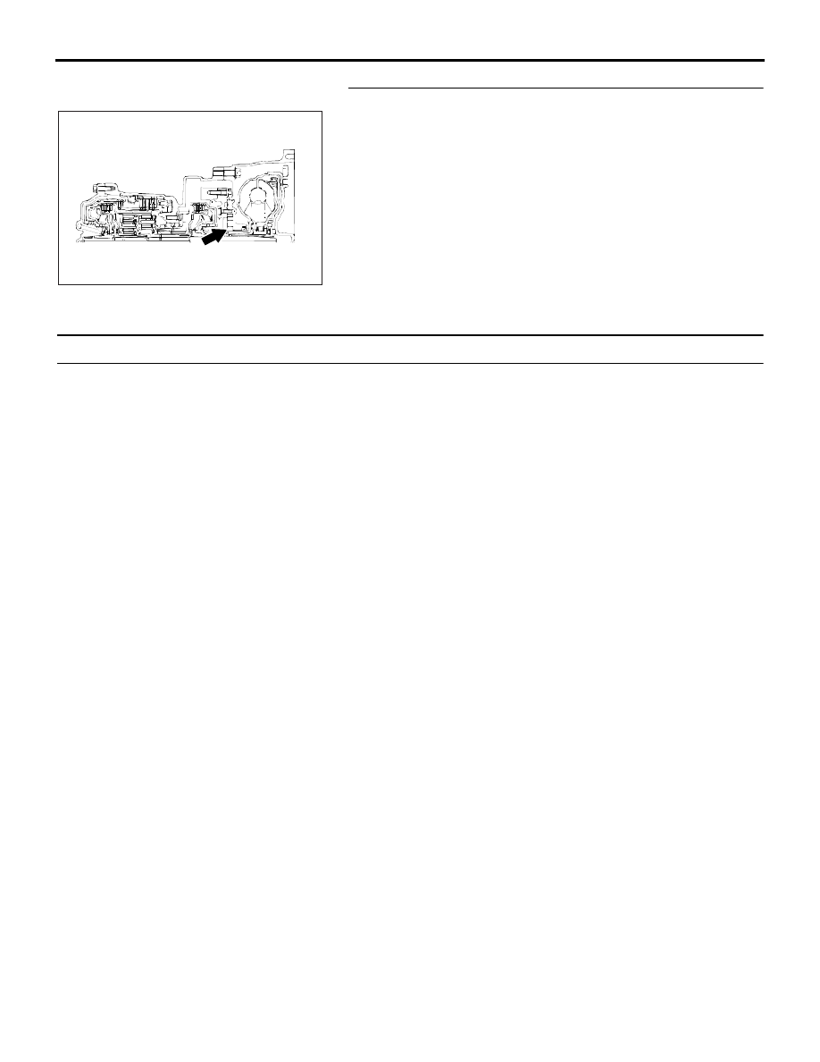
STEP 6. Check the oil pump.
(1) Remove the transmission assembly.
(2) Check the oil pump (incorrect installation, damage and etc.) 

and replace the oil pump assembly if necessary (The oil 
pump cannot be disassembled).Refer to GROUP 23B, 
Transmission 

P.23B-13

. Confirm that the malfunction 

symptom is eliminated.

Q: Is the symptom eliminated?

YES : The procedure is complete.
NO :  Start over at Step 1.

INSPECTION PROCEDURE 2: Does not Move Forward

.

COMMENT

If the engine is idling and the selector lever is shifted 
from "N" to "D" range and the vehicle does not drive 
forward then the cause is due to line pressure defect, 
under drive clutch or valve body malfunction.

.

TROUBLESHOOTING HINTS (THE MOST 
LIKELY CAUSES FOR THIS CONDITION:)

• Abnormal line pressure

• Malfunction of the underdrive solenoid valve

• Malfunction of the underdrive clutch

• Malfunction of the oil pump

• Malfunction of the valve body

• Malfunction of the A/T-ECU system
• Check RED brake system.

Circuit drawings

• Refer to circuit diagrams GROUP-

90

• Refer to configuration diagrams GROUP-

80

• Refer to component locations GROUP-

70

DIAGNOSIS

Required Special Tool:

• MB991958: Diagnostic Tool (MUT-III Sub Assembly)

• MB991824: V.C.I.

• MB991827: MUT-III USB Cable

• MB991910: MUT-III Main Harness A

AC001858

AUTOMATIC TRANSMISSION DIAGNOSIS

AUTOMATIC TRANSMISSION

23A-221

STEP 1. Using diagnostic tool MB991958, check actuator 
test item 02: Underdrive Solenoid Valve.

CAUTION

To prevent damage to diagnostic tool MB991958, always 
turn the ignition switch to the "LOCK" (OFF) position 
before connecting or disconnecting diagnostic tool 
MB991958. 
(1) Connect diagnostic tool MB991958 to the data link 

connector.

(2) Turn the ignition switch to the "ON" position.
(3) Set diagnostic tool MB991958 to the actuator test mode.

• Item 02: Underdrive Solenoid Valve.

• An audible clicking or buzzing should be heard when 

the underdrive solenoid valve is energized.

(4) Turn the ignition switch to the "LOCK" (OFF) position.

Q: Is the solenoid valve operating properly?

YES : Go to Step 2.
NO :  Repair or replace the underdrive solenoid valve. 

Refer to GROUP 23B, Valve Body 

P.23B-62

. Then 

confirm that the symptom is eliminated.

STEP 2. Check the hydraulic pressure.
Shift the selector lever to the sport mode then measure the 
hydraulic pressure of each element in 1st speed to check and 
see if each respective hydraulic pressure is within the range of 
standard pressure. Refer to 

P.23A-26

Hydraulic Pressure Test.

Q: Is the hydraulic pressure within the standard value?

YES : Go to Step 3.
NO :  Go to Step 4.

STEP 3. Check the underdrive clutch system.
(1) Remove the valve body cover and valve body. Refer to  

P.23A-304

, Transmission Assembly and GROUP 23B, 

Transmission 

P.23B-13

.

(2) Blow 108 kPa (15psi) compressed air into the underdrive 

clutch oil orifice of the transmission case, and check if the 
underdrive clutch piston moves and air pressure is 
maintained in that condition.

Q: Is the air pressure maintained?

YES : Go to Step 4.
NO :  Go to Step 6.

00DB076A

MB991910

DATA LINK

CONNECTOR

MB991824

MB991827

AC001859

UNDERDRIVE

CLUTCH OIL

ORIFICE

AB

AUTOMATIC TRANSMISSION DIAGNOSIS

AUTOMATIC TRANSMISSION

23A-222

STEP 4. Disassemble and clean the valve body.
Check the O-ring installation bolts for looseness and valve 
body for damage. Repair or replace the faulty parts. Refer to 
GROUP 23B, Valve Body 

P.23B-62

.

Replace the valve body assembly if the damages are thought 
to be irreparable. Then check the symptom.

Q: Is the symptom eliminated?

YES : The procedure is complete.
NO :  Go to Step 5.

STEP 5. Check the oil pump.
(1) Remove the transmission assembly.
(2) Check the oil pump (incorrect installation, damage and etc.) 

and replace the oil pump assembly if necessary (The oil 
pump cannot be disassembled). Refer to GROUP 23B, 
Transmission 

P.23B-13

. Then check the symptom.

Q: Is the symptom eliminated?

YES : The procedure is complete.
NO :   Start over at Step 1.

STEP 6. Check the underdrive clutch.
(1) Remove the transmission assembly.
(2) Check the facing for seizure and the piston seal ring for 

damage and interference with the retainer. Repair or 
replace the faulty parts. Refer to GROUP 23B, Underdrive 
Clutch and Input Shaf

P.23B-46

. Then check the symptom.

Q: Is the symptom eliminated?

YES : The procedure is complete.
NO :  Start over at Step 1.

VALVE BODY
ASSEMBLY

10DB117A

AC001858

AC001861

AUTOMATIC TRANSMISSION DIAGNOSIS

AUTOMATIC TRANSMISSION

23A-223

INSPECTION PROCEDURE 3: Does not Reverse

.

COMMENT

If the vehicle does not reverse when the selector 
lever is shifted from "N" to "R" range while the engine 
is idling, the cause is probably abnormal pressure or 
a malfunction of the reverse clutch, low-reverse 
brake, or valve body.

.

TROUBLESHOOTING HINTS (The most 
likely causes for this condition:)

• Abnormal reverse clutch pressure

• Abnormal low-reverse brake pressure

• Malfunction of the low-reverse solenoid valve

• Malfunction of the reverse clutch

• Malfunction of the low-reverse brake

• Malfunction of the valve body

• Malfunction of the A/T-ECU system
• Check RED brake system.

Circuit drawings

• Refer to circuit diagrams GROUP-

90

• Refer to configuration diagrams GROUP-

80

• Refer to component locations GROUP-

70

DIAGNOSIS

Required Special Tool:

• MB991958: Diagnostic Tool (MUT-III Sub Assembly)

• MB991824: V.C.I.

• MB991827: MUT-III USB Cable

• MB991910: MUT-III Main Harness A

STEP 1. Using diagnostic tool MB991958, check actuator 
test item 01: Low-Reverse Solenoid Valve.

CAUTION

To prevent damage to diagnostic tool MB991958, always 
turn the ignition switch to the "LOCK" (OFF) position 
before connecting or disconnecting diagnostic tool 
MB991958. 
(1) Connect diagnostic tool MB991958 to the data link 

connector.

(2) Turn the ignition switch to the "ON" position.
(3) Set diagnostic tool MB991958 to the actuator test mode.

• Item 01: Low-Reverse Solenoid Valve.

• An audible clicking or buzzing should be heard when 

the low-reverse solenoid valve is energized.

(4) Turn the ignition switch to the "LOCK" (OFF) position.

Q: Is the solenoid valve operating properly?

YES : Go to Step 2.
NO :  Repair or replace the low-reverse solenoid valve. 

Refer to GROUP 23B, Valve Body 

P.23B-62

. Then 

confirm that the symptom is eliminated.

00DB076A

MB991910

DATA LINK

CONNECTOR

MB991824

MB991827


Content   ..  418  419  420  421   ..