Mitsubishi 380. Manual - part 388


  Index      Mitsubishi     Mitsubishi 380 - service repair manual 2005 year


Search            


Content   ..  386  387  388  389   ..


Mitsubishi 380. Manual - part 388


AUTOMATIC TRANSMISSION DIAGNOSIS

AUTOMATIC TRANSMISSION

23A-92

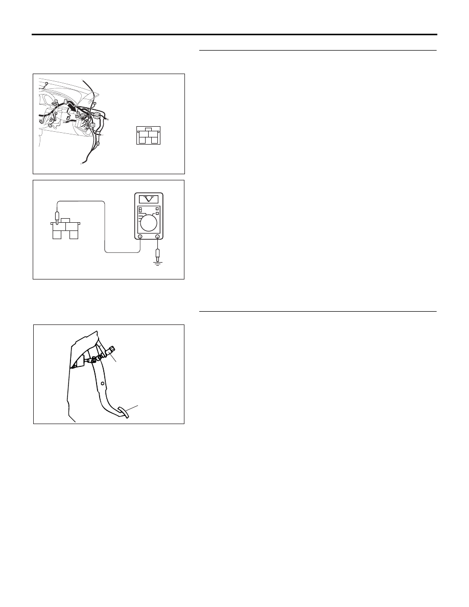
STEP 7. Measure the stoplamp switch output voltage to the 
ENGINE-ECU at connector C-30 by backprobing.
(1) Remove the stoplamp switch from the mounting bracket.
(2) Do not disconnect connector C-30.

(3) Measure the voltage between terminal 1 and ground by 

backprobing.

• When the switch button is out (closed circuit), voltage 

should equal battery positive voltage.

• When the switch button is depressed (open circuit), volt-

age should measure less than 1.0 volt.

Q: Is the measured voltage battery positive voltage with 

the switch button released (closed circuit), and less 
than 1.0 volt with the switch button depressed (open 
circuit)?
YES : 
Go to Step 9.
NO :  Go to Step 8.

STEP 8. Check the stoplamp switch.
Refer to GROUP 35A, On-vehicle Service 

− Stoplamp Switch 

Check 

P.35A-25

.

Q: Does the stoplamp switch pass the checks?

YES : Go to Step 9.
NO :  Replace the stoplamp switch. Refer to GROUP 35A, 

Brake Pedal 

P.35A-24

.

10DB091A

CONNECTOR: C-30

2

1

3

4

3

2

1

4

AC201041

C-30 HARNESS
CONNECTOR:
HARNESS SIDE

AH

ACX02208

BRAKE PEDAL

STOPLIGHT
SWITCH

AD

AUTOMATIC TRANSMISSION DIAGNOSIS

AUTOMATIC TRANSMISSION

23A-93

STEP 9. Measure the stoplamp switch output voltage at the 
ENGINE-ECU connector B-21 by using check harness 
special tool MB992044.
(1) Install the stoplamp switch into the mounting bracket if it 

was removed.

(2) Disconnect all the connectors from the ENGINE-ECU.
(3) Connect special tool MB992044 (check harness) between 

the ENGINE-ECU and the body-side harness connector.

(4) Measure the voltage between connector B-21 (terminal 18) 

and ground.

• When the brake pedal is depressed, voltage should 

measure battery positive voltage.

• When the brake pedal is not depressed, voltage should 

measure less than 1.0 volt.

Q: Is the measured voltage battery positive voltage with 

the brake pedal depressed (closed circuit), and less 
than 1.0 volt with the brake pedal released (open 
circuit)?
YES : 
Go to Step 12.
NO :  Go to Step 10.

16DB400A

COVER

ENGINE

CONTROL

UNIT

AIR

CLEANER

10DB092A

B-21 HARNESS

CONNECTOR:

COMPONENT SIDE

AUTOMATIC TRANSMISSION DIAGNOSIS

AUTOMATIC TRANSMISSION

23A-94

STEP10. Check ENGINE-ECU connector B-21 and 
stoplamp switch connector C-30 for loose, corroded or 
damaged terminals, or terminals pushed back in the 
connector.
Q: Are the connectors and terminals in good condition?

YES : Go to Step 11.
NO :  Repair or replace the damaged components. Refer to 

GROUP 00E, Harness Connector Inspection 

P.00E-2

.

16DB400A

COVER

ENGINE

CONTROL

UNIT

AIR

CLEANER

10DB091A

CONNECTOR: C-30

2

1

3

4

AUTOMATIC TRANSMISSION DIAGNOSIS

AUTOMATIC TRANSMISSION

23A-95

STEP 11. Check the harness for damage between 
ENGINE-ECU connector B-21 terminal 18 and stoplamp 
switch connector C-30 terminal 1.
Q: Is the harness wire in good condition?

YES : Go to Step 12.
NO :  Repair or replace the harness wire.

16DB400A

COVER

ENGINE

CONTROL

UNIT

AIR

CLEANER

10DB091A

CONNECTOR: C-30

2

1

3

4


Content   ..  386  387  388  389   ..