Mitsubishi 380. Manual - part 352
EMISSION CONTROL
ENGINE AND EMISSION CONTROL
17-76
EMISSION CONTROL
GENERAL DESCRIPTION
M1173000100314
The emission control system consists of the fol-
lowing subsystems:
• Positive crankcase ventilation system
• Evaporative emission system
• Exhaust emission control system
DIAGNOSIS
M1173000700112
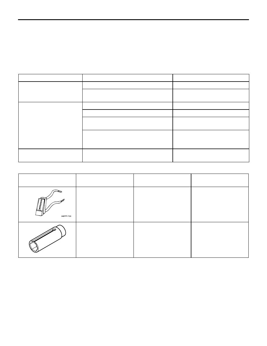
SPECIAL TOOLS
M1173000600193
SYMPTOM
PROBABLE CAUSE
REMEDY
Engine will not start or hard
to start
Vacuum hose disconnected or damaged
Repair or replace
Malfunction of the evaporative emission
purge solenoid
Repair or replace
Rough idle or engine stalls
Vacuum hose disconnected or damaged. Repair or replace
Malfunction of the positive crankcase
ventilation valve
Replace
Malfunction of the purge control system
Check the system; If there is a
problem, check its component
parts.
Excessive oil consumption
Positive crankcase ventilation line
clogged
Check positive crankcase
ventilation system
TOOL
TOOL NUMBER AND
NAME
SUPERSESSION
APPLICATION
MB995061
Purge flow indicator
MLR6890A
Part of MIT280220
Inspection of purge
control system
MD998770
Oxygen sensor wrench
MD998770-01 or General
service tool
Removal/installation of
heated oxygen sensor