Mitsubishi 380. Manual - part 351


  Index      Mitsubishi     Mitsubishi 380 - service repair manual 2005 year


Search            


Content   ..  349  350  351  352   ..


Mitsubishi 380. Manual - part 351


AUTO-CRUISE CONTROL

ENGINE AND EMISSION CONTROL

17-72

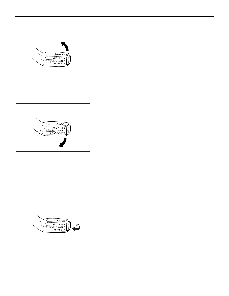
SPEED-INCREASE SETTING

1. Set to the desired speed.
2. Push the auto-cruise control switch in the direction of the 

arrow.

3. Check to be sure that acceleration continues while the 

switch is held, and that after it is released the constant 
speed at the time when it was released becomes the driving 
speed.

NOTE: Acceleration can be continued even if the vehicle 
speed has passed the high-speed limit [approximately 170 
km/h ]. But the speed when the auto-cruise control switch is 
released will be recorded as the high-speed limit.

SPEED-REDUCTION SETTING

1. Set to the desired speed.
2. Push the auto-cruise control switch in the direction of the 

arrow.

3. Check to be sure that deceleration continues while the 

switch is pressed, and that after it is released the constant 
speed at the time when it was released becomes the driving 
speed.

NOTE: When the vehicle speed reaches the low limit 
[approximately 40 km/h ] during deceleration, the 
auto-cruise control will be cancelled.

RETURN TO THE SET SPEED BEFORE 
CANCELLATION AND AUTO-CRUISE CONTROL 
CANCELLATION

1. Set the auto-cruise speed control.

2. When any of the following operations are performed while at 

constant speed during auto-cruise control, check if normal 
driving is resumed and deceleration occurs.

(1) The auto-cruise control switch is pulled in the direction of 

the arrow.

(2) The brake pedal is depressed.
(3) The selector lever is moved to the "N" range.

3. At a vehicle speed of 40 km/h or higher, check if when the 

"ACC/RES" switch is switched ON, the vehicle speed 
returns to the speed before auto-cruise control driving was 
cancelled, and constant speed driving occurs.

4. When the "CRUISE" (MAIN) switch is turned to the "OFF" 

while driving at constant speed, check if normal driving is 
resumed and deceleration occurs.

ACX01172

AE

ACX01172

AD

ACX01172

AG

AUTO-CRUISE CONTROL

ENGINE AND EMISSION CONTROL

17-73

AUTO-CRUISE CONTROL SYSTEM COMPONENT 

CHECK

M1172001700316

AUTO-CRUISE CONTROL SWITCH CHECK

1. Remove the auto-cruise control switch. (Refer to 

P.17-75

).

2. Measure the resistance between terminal 2 and terminal 3 

when each of the "COAST/SET", "ACC/RES", "CANCEL" 
and "CRUISE" (MAIN) switches is pressed. If measure 
values measured at the time correspond to those in the table 
below, the resistance values are correct.

STOPLIGHT SWITCH

1. Disconnect the connector.
2. Check for continuity between the terminals of the switch.

SWITCH POSITION

SPECIFIED CONDITION

"CRUISE" (MAIN) switch 
"OFF"

Open circuit

"CRUISE" (MAIN) switch "ON" Less than 2 ohms

"CANCEL" switch ON

Approximately 100 

"ACC/RES" switch ON

Approximately 887 

"COAST/SET" switch ON

Approximately 300 

1 2 3

AC203822AB

OFF

OFF

OFF

OFF

ON

ON

ON

ON

CAN

MAIN

RES

SET

2

3

MEASUREMENT 
CONDITION

TERMINAL 
CONNECTOR 
OF TESTER

SPECIFIED 
CONDITION

When brake pedal 
is depressed.

− 2 (for 

stoplamp circuit)

Less than 2 ohms

− 4 (for 

auto-cruise 
control circuit)

Open circuit

When brake pedal 
is not depressed.

− 2 (for 

stoplamp circuit)

Open circuit

− 4 (for 

auto-cruise 
control circuit)

Less than 2 ohms

ACX01180AB

AUTO-CRUISE CONTROL

ENGINE AND EMISSION CONTROL

17-74

THROTTLE POSITION SENSOR

Refer to GROUP 13A, On-vehicle Service 

− Throttle Actuator 

Control Motor Check 

13A-671

 (3.8L engine).

WARNING

If the  air intake duct is removed from the throttle 
body take great care to keep fingers away from the 
throttle plate. The drive motor has very high torque 
and is capable of random movement at any time. Do 
not under any circumstance activate the throttle plate 
by hand.
When removing the throttle body from the intake 
manifold disconnect the wiring first.During replace-
ment connect the wiring last.
Do not activate the throttle body using a DC supply to 
test the motor, as permanent damage to the throttle 
body will result.

TRANSMISSION INHIBITOR SWITCH ("N" 
POSITION)

Refer to GROUP 23A, On-vehicle Service 

− Essential Service 

P.23A-294

.

AUTO-CRUISE CONTROL

ENGINE AND EMISSION CONTROL

17-75

AUTO-CRUISE CONTROL

REMOVAL AND INSTALLATION

M1172001400467

WARNING

Before removal of the air bag module, refer to GROUP 52B, SRS Service Precautions 

P.52B-16

 and GROUP 52B, Air Bag Module and Clock Spring 

P.52B-237

.

17DB048A

AC209672

AC305701

1

7

6

5

4

3

2

8

41 ± 8 N·m
30 ± 6 ft-lb

9.0 ± 2.0 N·m
80 ± 17 in-lb

9

CONTROL SWITCH REMOVAL 
STEPS

1. AIR BAG MODULE <DRIVER’S 

SIDE> (REFER TO GROUP 52B, AIR 
BAG MODULES AND CLOCK 
SPRING 

P.52B-237

)

2. STEERING WHEEL ASSEMBLY 

(REFER TO GROUP 37, STEERING 
WHEEL 

P.37-23

)

3. LOWER COVER CAP
4. AUTO-CRUISE CONTROL SWITCH

CONTROL UNIT REMOVAL

5.  Engine ECU [REFER TO GROUP 

13A,  Engine ECU 

13A-675

SENSOR REMOVAL STEPS

6. TRANSMISSION INHIBITOR 

SWITCH (REFER TO GROUP 23B, 
AUTOMATIC TRANSMISSION)

7. THROTTLE BODY (BUILT-IN 

THROTTLE POSITION SENSOR 
AND THROTTLE ACTUATOR 
CONTROL MOTOR) (REFER TO 
GROUP 13A, THROTTLE BODY 

13A-660

8. ACCELERATOR PEDAL (BUILT-IN 

ACCELERATOR PEDAL POSITION 
SENSOR) (REFER TO GROUP 17, 
ACCELERATOR PEDAL 

P.17-9

)

9. STOPLIGHT SWITCH (REFER TO 

GROUP 35A, BRAKE PEDAL 

P.35A-24

)


Content   ..  349  350  351  352   ..