Mitsubishi 380. Manual - part 330
TRACTION CONTROL SYSTEM (TCL) DIAGNOSIS
TRACTION CONTROL SYSTEM (TCL)
13C-40
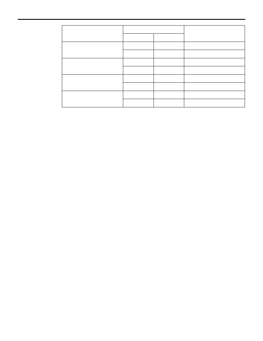
SIGNAL
TERMINAL NO.
NORMAL CONDITION
ABS (A-02)
SENSOR
FR wheel speed sensor
(A-01)
9
2
Less than 2 ohms
10
1
Less than 2 ohms
RR wheel speed sensor
(D-30)
8
1
Less than 2 ohms
19
2
Less than 2 ohms
FL wheel speed sensor
(A-04)
16
2
Less than 2 ohms
5
1
Less than 2 ohms
RL wheel speed sensor
(D-31)
6
1
Less than 2 ohms
17
2
Less than 2 ohms